Flow guiding structure of fan

A fan diversion and fan technology, which is applied to components of pumping devices for elastic fluids, non-variable pumps, machines/engines, etc., can solve the problem of ineffective dissipation of heat, low convection efficiency, and cold wind blowing The scope of the air is limited and other problems, to achieve the effect of increasing the air supply angle, enhancing the convection efficiency, and increasing the diffusion angle

Inactive Publication Date: 2013-08-21
林宸彰
View PDF5 Cites 0 Cited by
  • Summary
  • Abstract
  • Description
  • Claims
  • Application Information

AI Technical Summary

Problems solved by technology

[0002] Commonly used fans, such as general vertical fans or ceiling fans, use most of the blades to rotate to force the air to flow. The airflow direction is mainly located in the axial direction of the fan, and the convection efficiency is relatively low at the positions located on both sides of the fan, resulting in The heat in the location cannot be dissipated efficiently
In addition, this type of fan and ceiling fan are limited by the rotation angle before leaving the factory, so that the range of cold air blowing is quite limited. For people who are located in a relatively remote position indoors, they are often affected by the stuffy environment. This is the most commonly used fan. or problems with the structure of the ceiling fan

Method used


Image

  • Flow guiding structure of fan
  • Flow guiding structure of fan
  • Flow guiding structure of fan

Examples


Embodiment 1

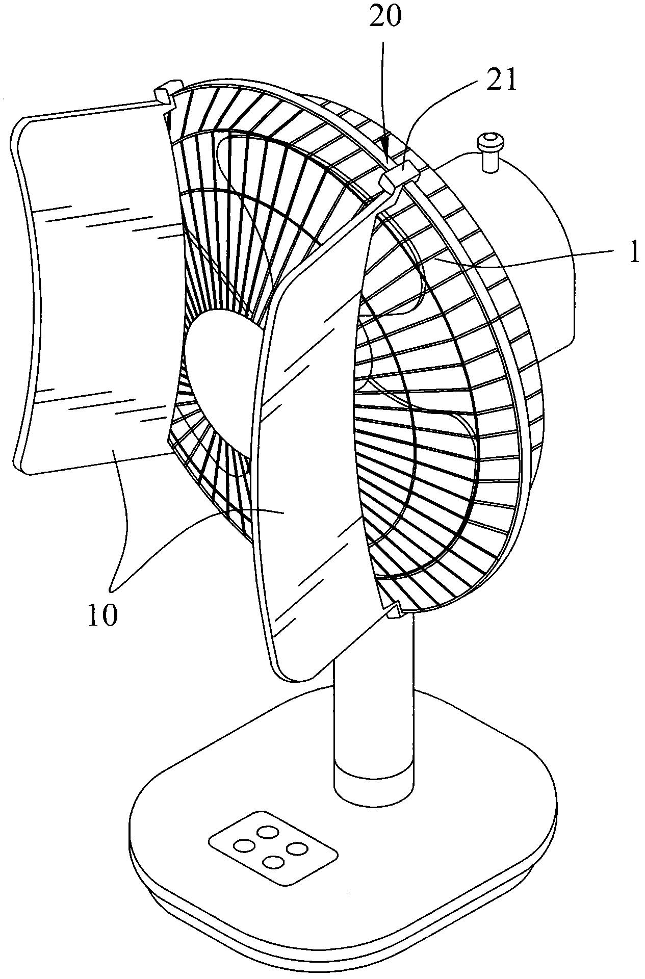
[0025] Please refer to figure 1 and figure 2 . In a preferred embodiment of the present invention, the fan guide structure is used in combination with a fan, which includes a vertical fan and a ceiling fan suspended from the ceiling. In this embodiment, the fan guide structure structure combined with the vertical fan Narrate.

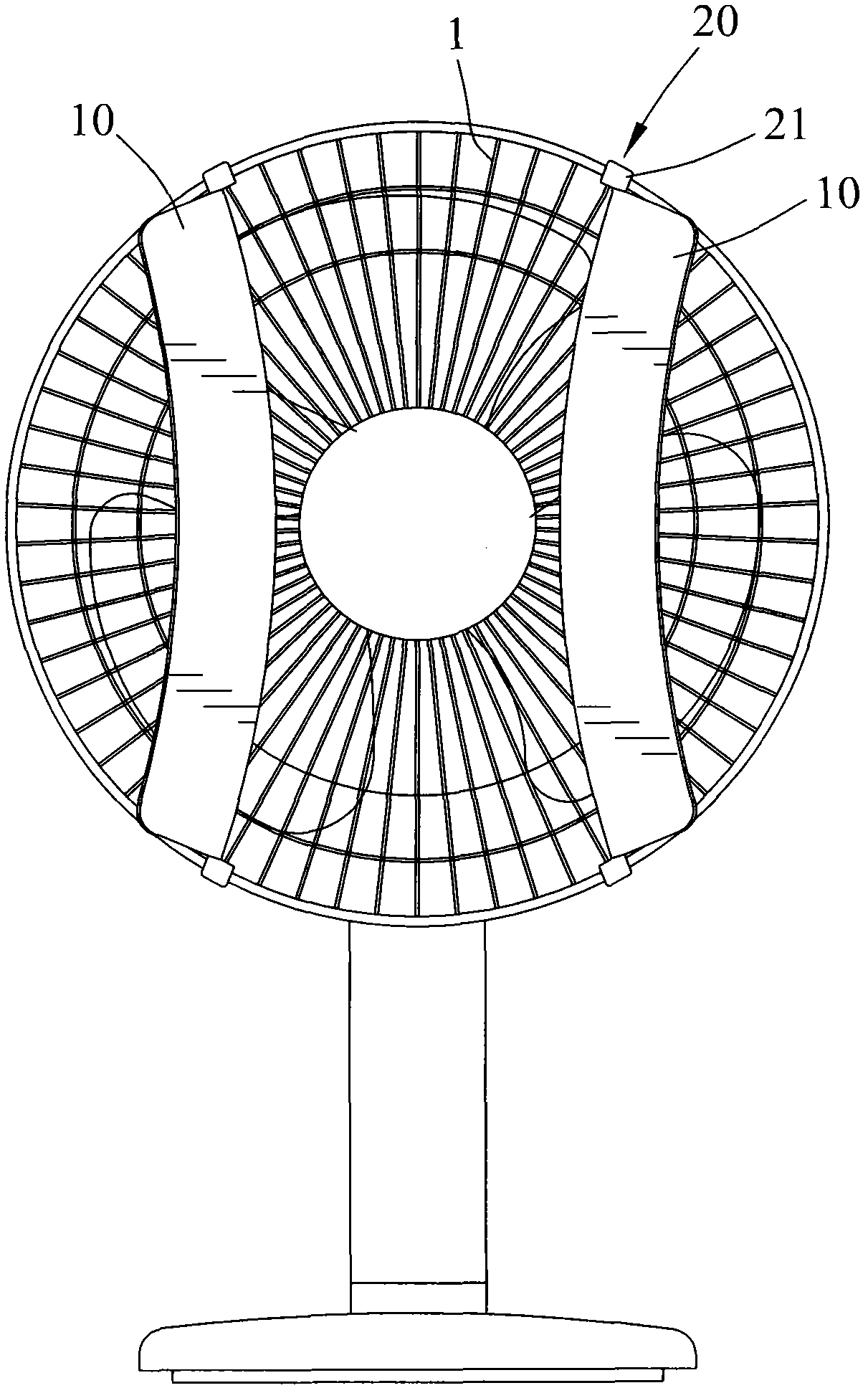
[0026] The fan guide structure of the present invention includes at least one guide plate 10 and at least one connecting portion 20. More specifically, the number of guide plates 10 is two, and the number of connecting portions 20 is also two.

[0027] The baffle 10 is straddled in front of the air outlet position of the fan. The baffle 10 is located on the side of the fan center and does not overlap with the center of the fan to avoid completely blocking the axial airflow of the fan. Therefore, the baffle 10 mainly extends diagonally outward It is used to guide the airflow to the side of the fan. Preferably, the baffle 10 has an arc surface for guiding t...

Embodiment 2

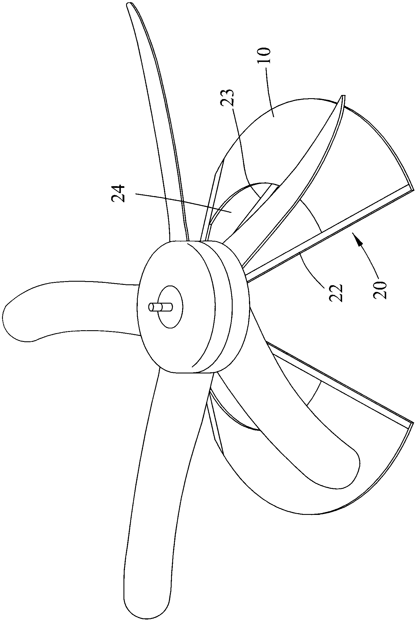
[0030] Please refer to image 3 and Figure 4 . The fan guide structure used in combination with the ceiling fan includes at least one fan-shaped guide plate 10. More specifically, as shown in the figure, the two guide plates 10 are more effective, and the top of the two fan-shaped guide plates 10 is formed with a corresponding The connecting part 20 in the shape of the ceiling fan joint, Figure 4 The connecting part 20 shown is matched with the hollow ring plate of the circular structure under the ceiling fan. Of course, it can also be combined with the different parts of the ceiling fan. The connecting part needs to be designed correspondingly according to the shape of the connecting part. The connecting portion 20 adopts a hollow ring plate corresponding to the circular structure below the ceiling fan, and also has a deflector 10 that can be adjusted at an angle of 360° relative to the ceiling fan.

[0031] The fan-shaped baffle 10 is combined with the ceiling fan through t...


PUM


Abstract

The invention relates to a flow guiding structure of a fan, wherein the flow guiding structure of a fan is arranged on the fan, and comprises at least one flow guiding plate and at least one connecting part, wherein the flow guiding plate is spanned in front of the air outlet position of the fan; the flow guiding plate is positioned at the central side edge of the fan and is not overlapped with the center of the fan; the flow guiding plate extends outwards obliquely so as to introduce the air flow into the side edge of the fan; and the flow guiding plate is connected on the fan by the connecting part, therefore, the flow guiding structure of the fan provided by the invention can be combined with the fan or a ceiling fan, so that the air flow formed by the fan not only can converge on the axial direction of the fan, but also can disperse to the side edge of the fan moderately, furthermore, the air feeding angle of the fan can be increased greatly, and the convection efficiency at the periphery of the fan can be improved, so that the dispersing angle of the air flow of the fan can be increased.

Description

Technical field [0001] The present invention relates to a fan flow guide structure, in particular to a fan flow guide structure that can guide airflow to the side of the fan. Background technique [0002] Commonly used fans, such as general vertical fans or ceiling fans, use most of the blades to rotate to force the flow of gas. The airflow direction is mainly located in the axial direction of the fan, and the positions on both sides of the fan have lower convection efficiency, resulting in The heat at this location cannot escape effectively. In addition, these fans and ceiling fans are limited by the rotation angle before leaving the factory, so that the range of cold air blowing is quite limited. For people located in relatively remote places in the room, they are often affected by the sultry environment. This is the commonly used fan. Or the problem of ceiling fan structure. Summary of the invention [0003] In view of this, the purpose of the present invention is to provide ...

Claims


Application Information

Patent Timeline
Patent Type & Authority Patents(China)
IPC IPC(8): F04D29/54
Inventor 林宸彰
Owner 林宸彰
Why Eureka
Try Eureka