Atomized liquid oral cleaning appliance

An oral cleaning and liquid technology, which is applied in the direction of cleaning the tooth cavity, etc., can solve the problems of regular replacement and expensive gas tanks

Active Publication Date: 2012-05-23
KONINKLIJKE PHILIPS ELECTRONICS NV
View PDF7 Cites 11 Cited by
  • Summary
  • Abstract
  • Description
  • Claims
  • Application Information

AI Technical Summary

Problems solved by technology

Therefore, the use of these devices is generally expensive as the gas tanks must be replaced periodically; the high pressure arrangement also presents certain design / engineering challenges

Method used


Image

  • Atomized liquid oral cleaning appliance
  • Atomized liquid oral cleaning appliance
  • Atomized liquid oral cleaning appliance

Examples


Embodiment Construction

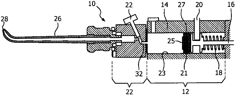
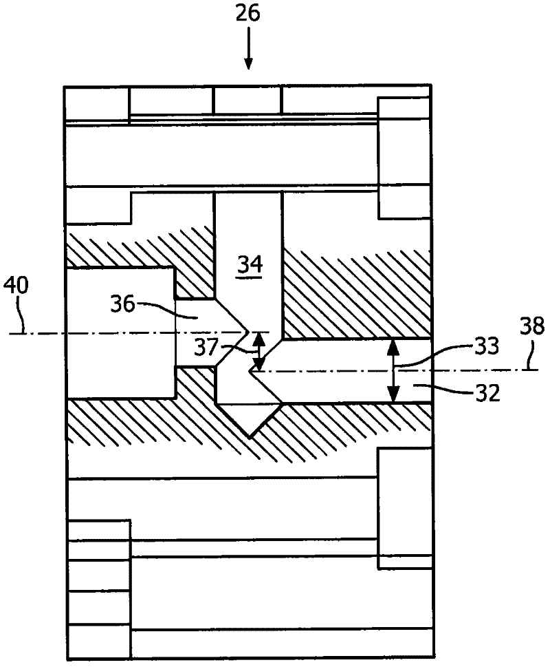
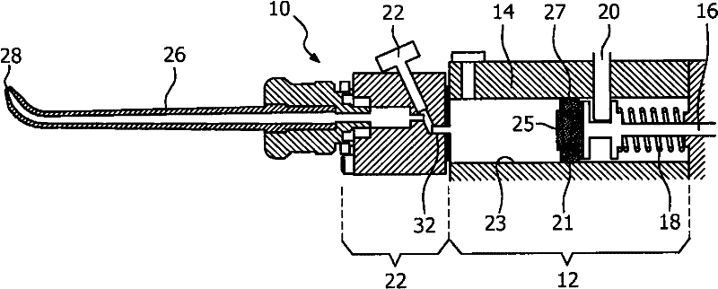
[0008] figure 1 An oral cleaning device using liquid droplets for cleaning produced by a low pressure gas system is shown. The device 10 includes a spring assembly 12 . The spring assembly 12 includes a hollow body 14 having a piston 16 and a spring 18 mounted therein for reciprocating movement. Piston 16 is moved to the rear of body 14 by user operation of an actuating element or button 20 engaged to the piston against the action of spring 18 . The front end 21 of the piston comprises a head element having an airtight connection with the inner wall 23 of the main body 14 . The front end has a raised central portion 25 with a surrounding grooved portion 27 . Upon releasing the actuating member and effecting the forward movement of the piston (pushed by the action of the spring 18), the head member pushes the air present in the body 14 into the mixing chamber 22, as will be described in more detail below and described in figure 2 shown in . With each application of air mo...


PUM


Abstract

The oral cleaning appliance includes an assembly for generating low-pressure bursts of gas in the range of 2-7 bar, directed to a mixing chamber portion of the appliance. A pump provides successive doses of liquid to the mixing chamber. The mixing chamber includes an outlet for liquid droplets produced by the interaction of the gas and the liquid in the mixing chamber. The gas inlet line to the mixing chamber has an internal diameter in the range of 1 -5 mm. The center line of the gas inlet line is offset from the center line of the liquid droplet outlet line by a distance in the range of 1 -5 mm.

Description

technical field [0001] The present invention is directed to an atomized liquid / droplet oral cleaning device that uses pressurized gas to generate droplets, and more particularly to a low pressure gas assembly for such a device. Background technique [0002] Liquid atomized spray / droplet oral cleaning devices include a source of pressurized gas (usually air), and a source of liquid (usually water) that are directed towards the mixing chamber portion of the device to produce a spray or stream of liquid droplets. The droplets are then directed through the nozzle assembly and out its exit tip to the selected area of ​​the tooth to be cleaned. Typically, the selected area is the interdental area, but the device can be used to clean the entire area of ​​the teeth, including around orthodontic fixtures. [0003] The source of pressurized gas can be CO 2 Air tank or similar source of high pressure air (usually up to 900psi). Therefore, the use of these devices is generally expens...

Claims


Application Information

Patent Timeline
Patent Type & Authority Applications(China)
IPC IPC(8): A61C17/02A61C17/028
CPCA61C17/0202A61C17/028A61C17/0217
Inventor T·G·克洛斯特J·J·M·詹森A·K·约翰逊
Owner KONINKLIJKE PHILIPS ELECTRONICS NV
Why Eureka
Try Eureka