
Comb segment for a circular comb

A needle plate seat and cylinder technology, which is applied in combing machines, textiles, papermaking, fiber processing, etc., can solve the problems of insufficient or even impossible cleaning, reduced carding effect, poor accessibility, etc., and achieve rapid and Economical manufacture and assembly, good carding effect, mechanically robust effect

Active Publication Date: 2014-07-30
STAEDTLER & UHL
View PDF2 Cites 0 Cited by
  • Summary
  • Abstract
  • Description
  • Claims
  • Application Information

AI Technical Summary

Problems solved by technology

This leads to poor accessibility of the intermediate spaces between adjacent teeth and / or adjacent tooth rows of the cylinder needle holder, so that cleaning of the cylinder needle holder with a high tooth density is not sufficient or even impossible
But in structures with a large intermediate space, the combing effect is reduced

Method used


Image

  • Comb segment for a circular comb
  • Comb segment for a circular comb
  • Comb segment for a circular comb

Examples


Embodiment Construction

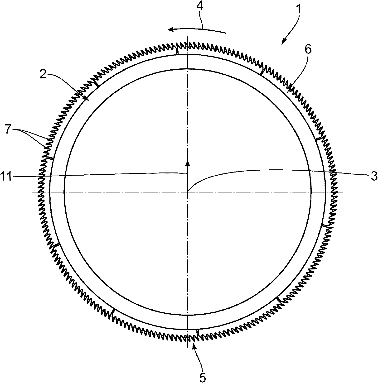
[0022] figure 1 The circular comb 1 shown in has a hollow cylindrical combing cylinder 2 with an axis of rotation 3 . A total of 10 cylinder needle holders 5 are mounted on the combing cylinder 2 along the direction of rotation 4 . The axial length of the cylinder needle plate seat 5 parallel to the axis of rotation 3 defines the combing area of ​​the circular comb 1 . Each cylinder needle plate seat 5 includes a plurality of identical punched combs 6 which are basically arranged sequentially along the direction of the rotation axis 3 , wherein each comb 6 has a plurality of teeth 7 . In the illustrated embodiment, the comb blade 6 is preassembled as a so-called tie rod and fixed on the combing cylinder 2 by clamps. Or, tie bar also can be connected with combing cylinder 2 by screw. Comb sheet 6 also can not be preloaded, but is directly contained on the combing cylinder 2 with group structure and is bonded with it.

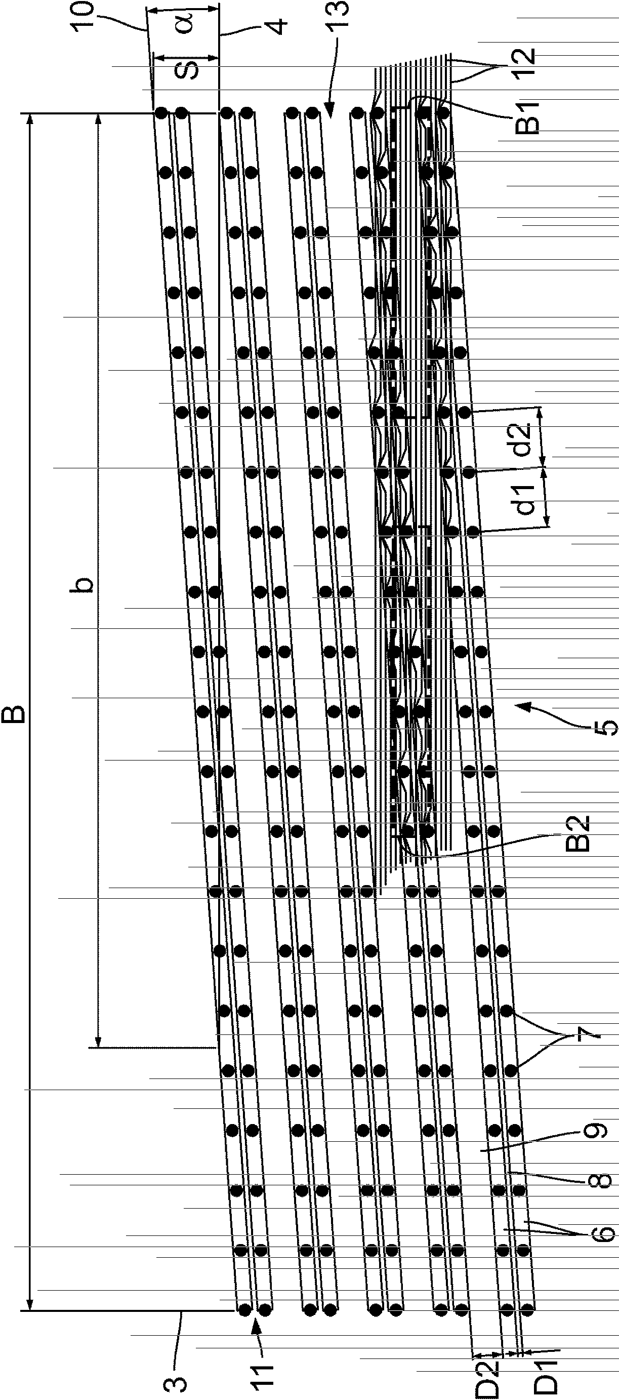
[0023] figure 2 The cylinder needle bar seat 5 is sch...


PUM

PropertyMeasurementUnit
thicknessaaaaaaaaaa

Abstract

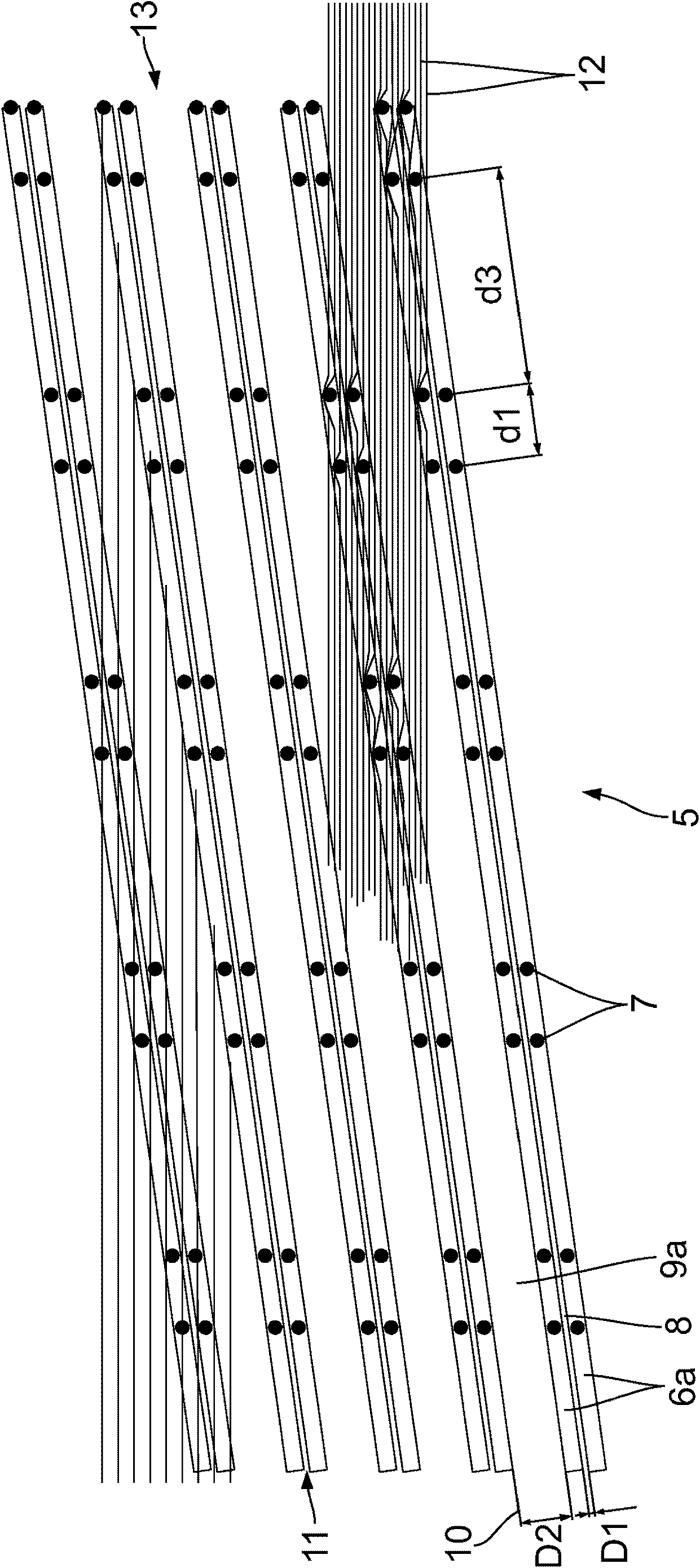
The invention relates to a comb segment for a circular comb of a comb roller for combing cotton, comprising a plurality of tooth rows (6; 6a) disposed adjacent to each other in the direction of a rotary axis (3) of the comb roller (2), having a row circumferential direction (10) and each having a plurality of teeth (7) disposed adjacent to each other in the row circumferential direction (10), wherein the comb segment (5) can be rotated about the rotary axis (3) in a direction of rotation (4) in the assembled state on the comb roller (2), the tooth rows (6; 6a) are disposed diagonally relative to the rotary axis (3), so that the row circumferential direction (10) and the direction of rotation (4) form an angle of approach a, at least one spacer (8, 9; 8, 9a) is provided between two adjacent tooth rows (6; 6a), and a tooth row distance (D1; D2) between two adjacent tooth rows (6; 6a) measured perpendicular to the row circumferential direction (10) varies cyclically.

Description

technical field [0001] The invention relates to a cylinder needle bar seat (Kammsegment) for a circular comb of a combing machine for carding cotton / cotton products. Background technique [0002] Combs for combing machines are known from previous publications, which combs are provided with at least one carding element on a base body, which engages the cotton fibers to be carded. The effective combing area of ​​the circular comb can be, for example, 78°, 90°, 111° or 180° of the outer wire circumference of the circular comb or possibly also the entire circumference. A circular comb with an active carding area along the entire circumference is called a 360° circular comb. Needles, needle strips, serrated wire segments, comb teeth or serrated punched parts are used as carding elements, wherein the structure of several carding elements is also called cylinder needle plate holder or tie rod. [0003] Announced by DE3007245A1 can be set in a combing cylinder The cylinder needl...

Claims


Application Information

Patent Timeline
Patent Type & Authority Patents(China)
IPC IPC(8): D01G19/10
CPCD01G19/105D01G19/10
Inventor F·亨宁格
Owner STAEDTLER & UHL
Learn More