Circular comb fitting

A technology of card clothing and carding needles, which is applied in the field of cylinder rollers, can solve problems such as fiber fret defects that cannot be ruled out, and achieve the effects of improving machine operation performance, reducing the number of bonding errors, and soft fiber handover

Active Publication Date: 2014-06-25
STAEDTLER & UHL
View PDF11 Cites 0 Cited by
  • Summary
  • Abstract
  • Description
  • Claims
  • Application Information

AI Technical Summary

Problems solved by technology

Although on the one hand the carding result is thus improved, on the other hand thread defects of the subsequently processed fiber product cannot be ruled out in this way.

Method used


Image

  • Circular comb fitting
  • Circular comb fitting
  • Circular comb fitting

Examples


Embodiment Construction

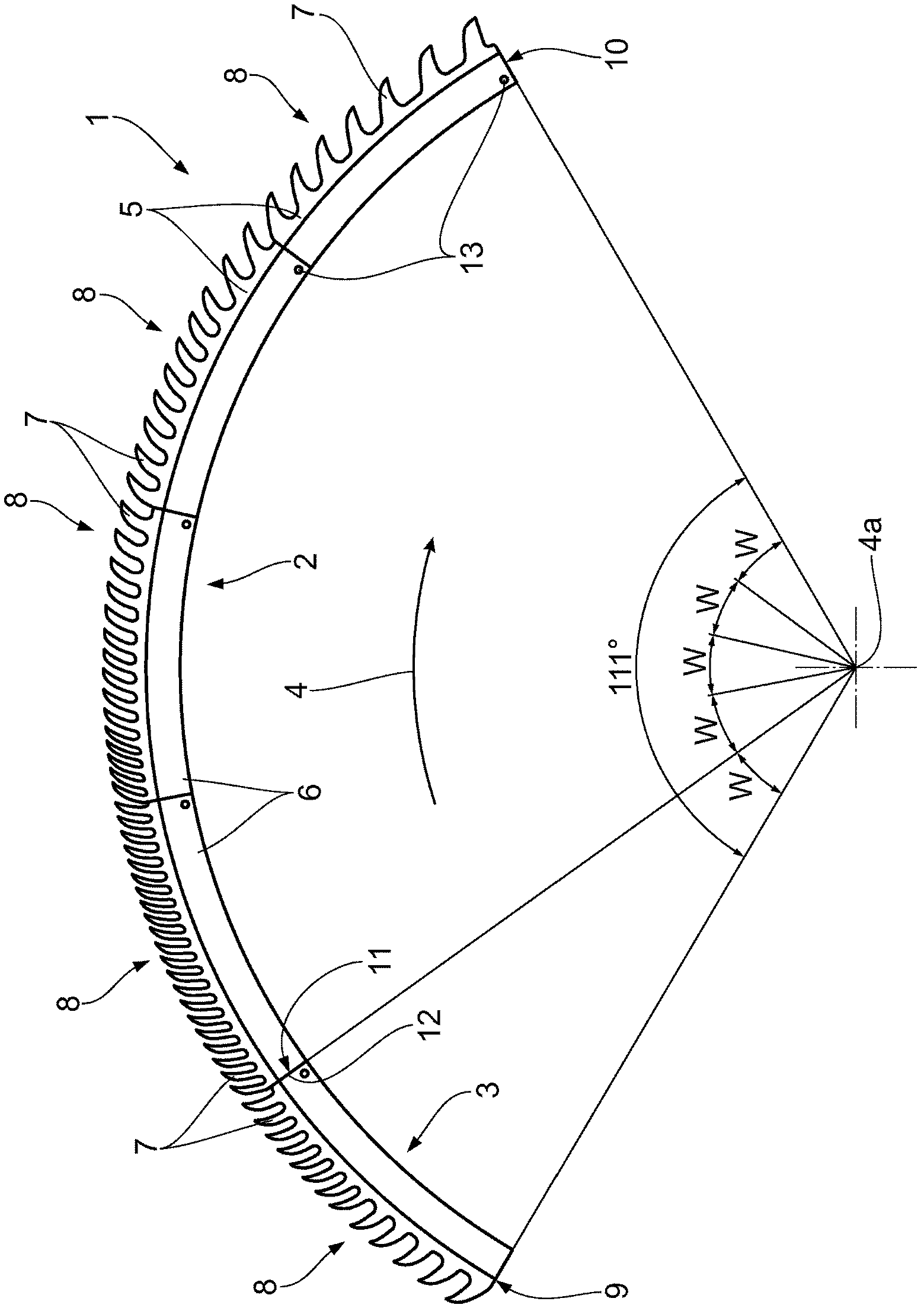
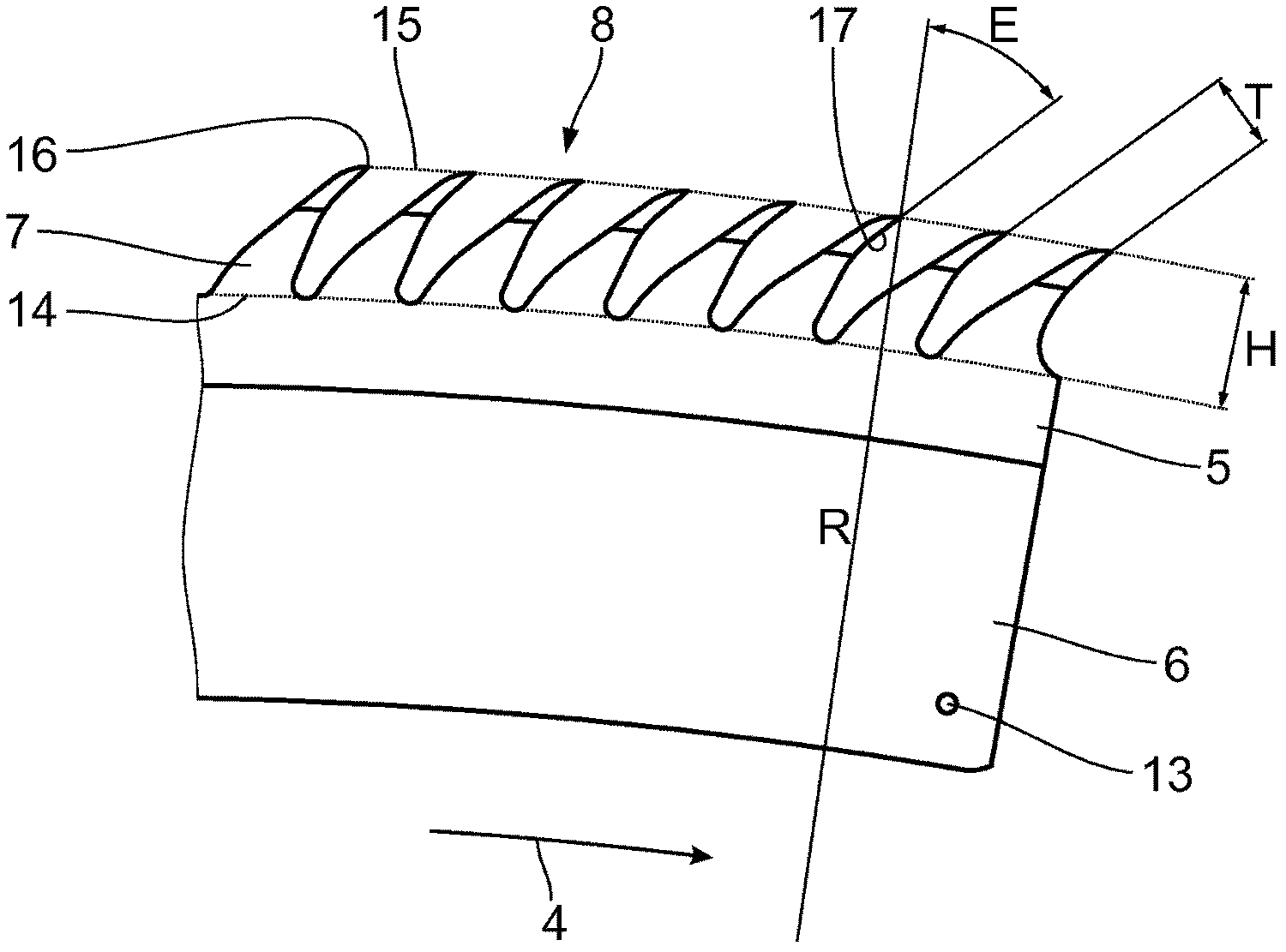
[0021] exist figure 1 The card clothing 1 of the circular comb of the textile combing machine shown in includes a first cylinder needle seat area 2 and a second cylinder needle bar seat area 3 . Two cylinder needle plate seats 2, 3 are arranged side by side along the direction of the rotation axis 4a of a cylinder roller not shown, and are formed by zigzag stamping parts 5 arranged sequentially along the direction of the rotation axis 4a of the cylinder roller, which The saw-tooth stamping 5 has teeth 7 extending away from the root 6 . The saw-tooth stamped part 5 , also called ring gear or tooth plate, can also be made of a saw-toothed strip.

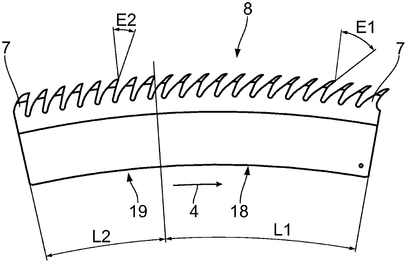
[0022] The configuration of the card clothing in the axial direction, ie in the direction of the axis of rotation 4a, will be described below. By using spacers without teeth and / or of different thicknesses, ie can have dimensions along the axis of rotation 4a, the sawtooth stampings 5 ​​can be positioned at a distance from one anothe...


PUM


Abstract

The invention relates to a comb fitting (1) for a comb roller of a textile machine rotatable about a rotary axis (4a), in particular of a combing machine and particularly for a circular comb, comprising at least one first and one second comb segment region (2, 3) disposed one after the other as seen in a direction of rotation (4) of the comb roller and formed by saw tooth punch parts (5) disposed adjacent to each other in the direction of the rotary axis (4a) and having teeth (7) extending away from a foot part (6), wherein a configuration of the teeth (7) within the first comb segment region (2) changes, so that the combing action of the teeth (7) opposite to the direction of rotation increases, and wherein the teeth (7) within the second comb segment region (3) are configured so that the combing action within the second comb segment region (3) is less than on the end (11) of the first comb segment region (2) as seen opposite the direction of rotation (4), and a configuration of the teeth (7) within the second comb region (3) changes so that the combing action of the teeth (7) is reduced opposite to the direction of rotation (4).

Description

technical field [0001] The invention relates to a card clothing for a cylinder roll, in particular for a circular comb, for a textile machine, in particular a combing machine, which cylinder roll is rotatable about an axis of rotation. Background technique [0002] A combing machine is known from CH673290A5 and DE102007010405A1. This combing machine has a cyclic flow of its working cycle. The fiber bundles of the batt are combed with a nipper device through the carding zone of a rotating circular comb equipped with a sliver. The uncombed batt is then replenished and the nipper unit moves onto the delivery rollers. As a result, the carded fiber bundles are deposited on the previously carded batt, combined with it and discharged. The top comb ensures that uncombed fibers and impurities attached to the uncombed batt are combed or blocked. The supplementary supply of batt is then combed out, thus starting a new carding cycle, which is also called a combing cycle. [0003] T...

Claims


Application Information

Patent Timeline
Patent Type & Authority Patents(China)
IPC IPC(8): D01G19/10
CPCD01G19/105
Inventor F·亨宁格
Owner STAEDTLER & UHL
Why Eureka
Try Eureka