Valve to myocardium tension members device and method

a technology of tension member and valve, which is applied in the field of repair of mitral valve insufficiency and the reduction of myocardial wall tension, can solve the problems of increasing the diameter of the mitral valve annulus, and achieve the effect of reducing wall stress and improving chamber performan

Inactive Publication Date: 2006-08-31
EDWARDS LIFESCIENCES LLC
View PDF99 Cites 203 Cited by
  • Summary
  • Abstract
  • Description
  • Claims
  • Application Information

AI Technical Summary

Benefits of technology

[0005] The present invention pertains to a device and method for mitral valve repair. The mitral-valve is generally defined as its leaflets or cusps, but in reality, it actually consists of the entire left ventricle chamber. By creating an improved chamber geometry, both chamber and valve function will be improved. The device of the present invention and method for valve repair / replacement can include treatment for chronic heart failure by reducing left ventricular wall tension.
[0011] More than one tension member can be used. Additionally, a transverse tension member can be placed across the chamber generally perpendicular to the other tension members to further alter the geometry of the heart, reducing wall stress and improving chamber performance.

Problems solved by technology

First, chamber dilation and associated high wall stresses increase the diameter of the mitral valve annulus.

Method used


Image

  • Valve to myocardium tension members device and method
  • Valve to myocardium tension members device and method
  • Valve to myocardium tension members device and method

Examples


Embodiment Construction

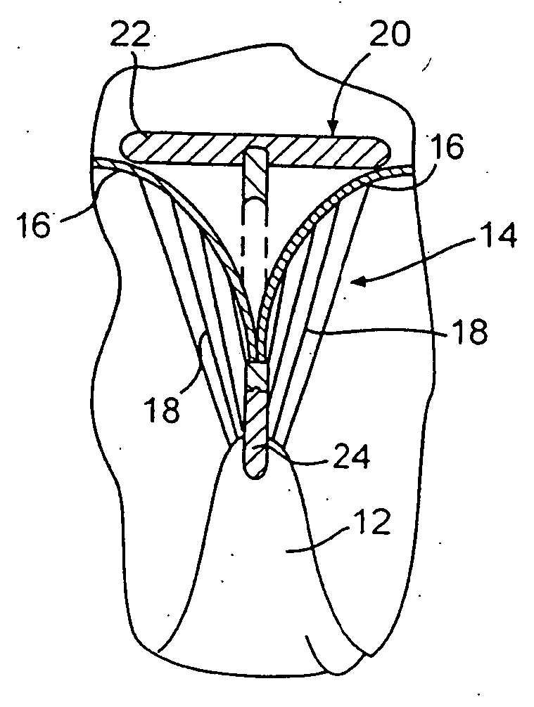
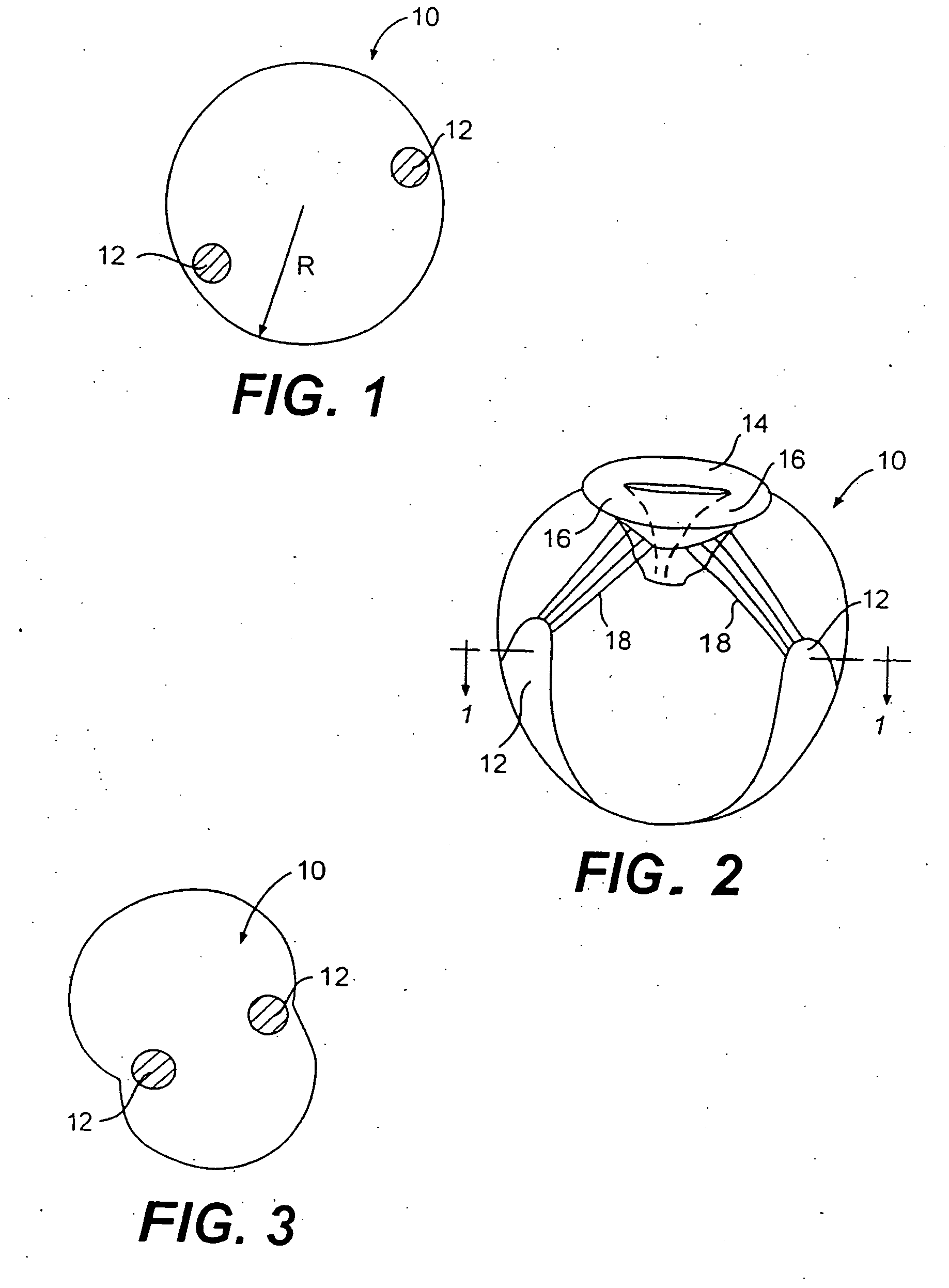
[0033] Referring now the drawings wherein like reference numerals refer to like elements throughout the several views, FIG. 1 shows a transverse cross section of the left ventricle 10 of a failing heart taken from FIG. 2. The papillary muscles 12 are shown in cross section. FIG. 2 is a vertical cross section of human heart 10. A mitral valve is disposed near the top of left ventricle 10. Mitral valve 14 includes two leaflets or cusps 16. Chordae 18 extend between leaflets 16 and papillary muscles 12.

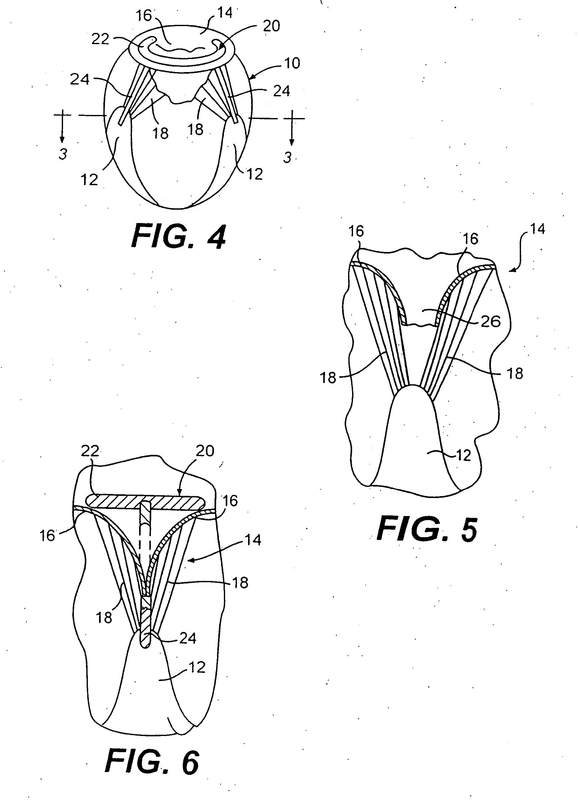
[0034]FIG. 3 is a cross section of heart 10 modified from that shown in FIG. 1 by placement of valve repair device 20 in accordance with the present invention as shown in FIG. 4. FIG. 4 is a vertical cross section of left ventricle 10 with geometry modified by device 20. In this embodiment of the invention, device 20 includes a basal anchor 22 such as an annuloplasty or suture ring sewn proximate the annulus of valve 14. Extending from basal anchor 22 are elongate tension members 24. Ea...


PUM


Abstract

A device for heart valve repair including at least one tension member having a first end and second end. A basal anchor is disposed at the first end of the tension member and a secondary anchor at the second end. The method includes the steps of anchoring the basal anchor proximate a heart valve and anchoring the secondary anchor at a location spaced from the valve such that the chamber geometry is altered to reduce heart wall tension and / or stress on the valve leaflets.

Description

BACKGROUND OF THE INVENTION [0001] The present invention pertains generally to the field of heart valve repair. More specifically, the present invention pertains to a device and method for the reduction of myocardial wall tension and the repair of mitral valve insufficiency. [0002] Dilated cardiomyopathy is often accompanied by mitral valve insufficiency. There are several reasons for the presence of mitral valve insufficiency associated with a dilated heart. First, chamber dilation and associated high wall stresses increase the diameter of the mitral valve annulus. Additionally, as the heart dilates, the positioning of the papillary muscles is altered. Papillary muscles and chordae in a dilated heart will have moved both radially away and down from the mitral valve. This rearrangement of the vascular apparatus and enlargement of the annulus prevent the valve from closing properly. [0003] Currently mitral valve insufficiency is treated by either repairing or replacing the valve. Sur...

Claims


Application Information

Patent Timeline
Patent Type & Authority Applications(United States)
IPC IPC(8): A61F2/02A61F2/24A61F2/00
CPCA61B2017/048A61F2/2445A61F2/2454A61F2/2457A61F2/2463A61F2/2487Y10S623/90
Inventor MORTIER, TODD J.SCHWEICH, CYRIL J. JR.
Owner EDWARDS LIFESCIENCES LLC
Why Eureka
Try Eureka