Hermetic feedthrough terminal assembly with wire bond pads for human implant applications

a technology of wire bonding pads and feedthrough terminals, which is applied in the direction of feed-through capacitors, fixed capacitor details, therapy, etc., can solve the problems that solders and conductive adhesives cannot be applied directly to such pin materials, and the proper operation of pacemakers is seriously disrupted, and the effect of weak tension

Active Publication Date: 2006-11-16
WILSON GREATBATCH LTD
View PDF50 Cites 218 Cited by
  • Summary
  • Abstract
  • Description
  • Claims
  • Application Information

AI Technical Summary

Benefits of technology

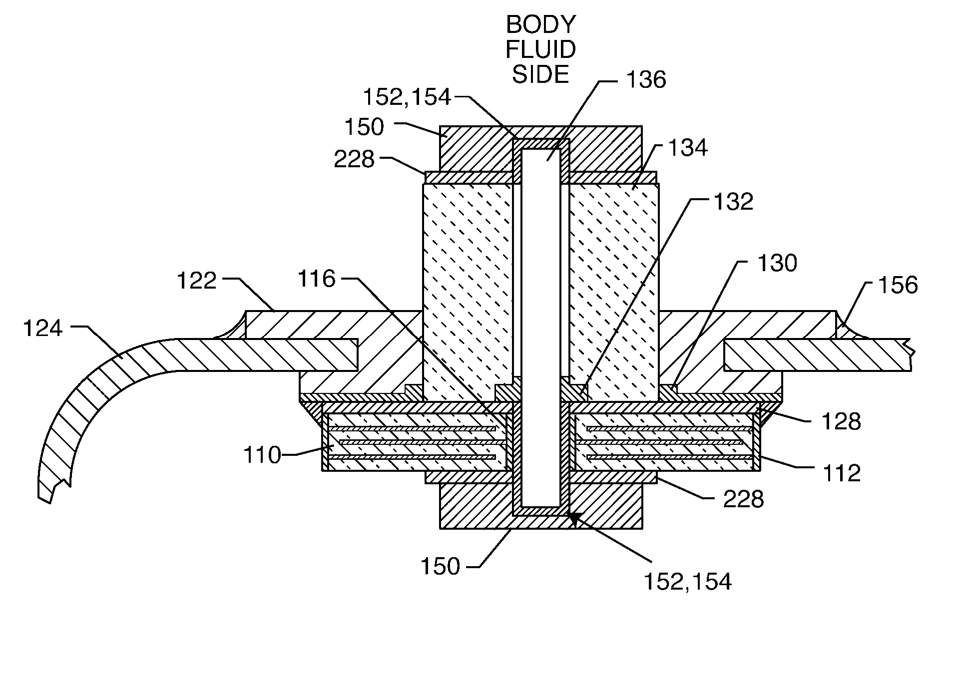
[0018] It should be noted that if lead-attachment is made by soldering or the like, the Kovar or Alloy 42 pad is generally not required. However, during ultrasonic or thermal wire bonding, considerable energy is imparted into the structure. Accordingly, in this case, a Kovar pad is desired to dissipate energy away from the underlying ceramic substrate or feedthrough capacitor structure. When wire bonding using thermosonic or ultrasonic energy, it is desirable to also use an alumina substrate which is co-bonded to the ceramic capacitor. This alumina substrate, when it is co-bonded, distributes the wire bonding shock and vibration forces across the entire surface of the ceramic capacitor. In general, ceramic materials, and capacitor dielectrics in particular, are strong in compression but very weak in tension. The relatively strong co-bonded alumina substrate helps protect the relatively weak barium titanate, strontium titanate or equivalent high K dielectric used in the ceramic capacitor from fracturing or forming micro-cracks during application of these wire bonding forces. As a general rule, as one raises the dielectric constant, K, of a ceramic material, the structurally weaker it becomes. A low K alumina or aluminum oxide substrate is generally much stronger than barium titanate or other high K ceramics and is able to withstand these wire bonding forces. In this way, tension, shear and impact forces do not build up or become excessive in the capacitor dielectric. Various substrates are well known in the art with wire bond pads and are typically used in combination with hybrid circuit electrical connections and the like.

Problems solved by technology

However, the lead wires can also undesirably act as an antenna and thus tend to collect stray electromagnetic interference (EMI) signals for transmission into the interior of the medical device.
Sinai Medical Center and other researchers have demonstrated that stray EMI, such as RF signals produced by cellular telephones, can seriously disrupt the proper operation of the pacemaker.
All of these situations can be dangerous or life threatening for a pacemaker-dependant patient.
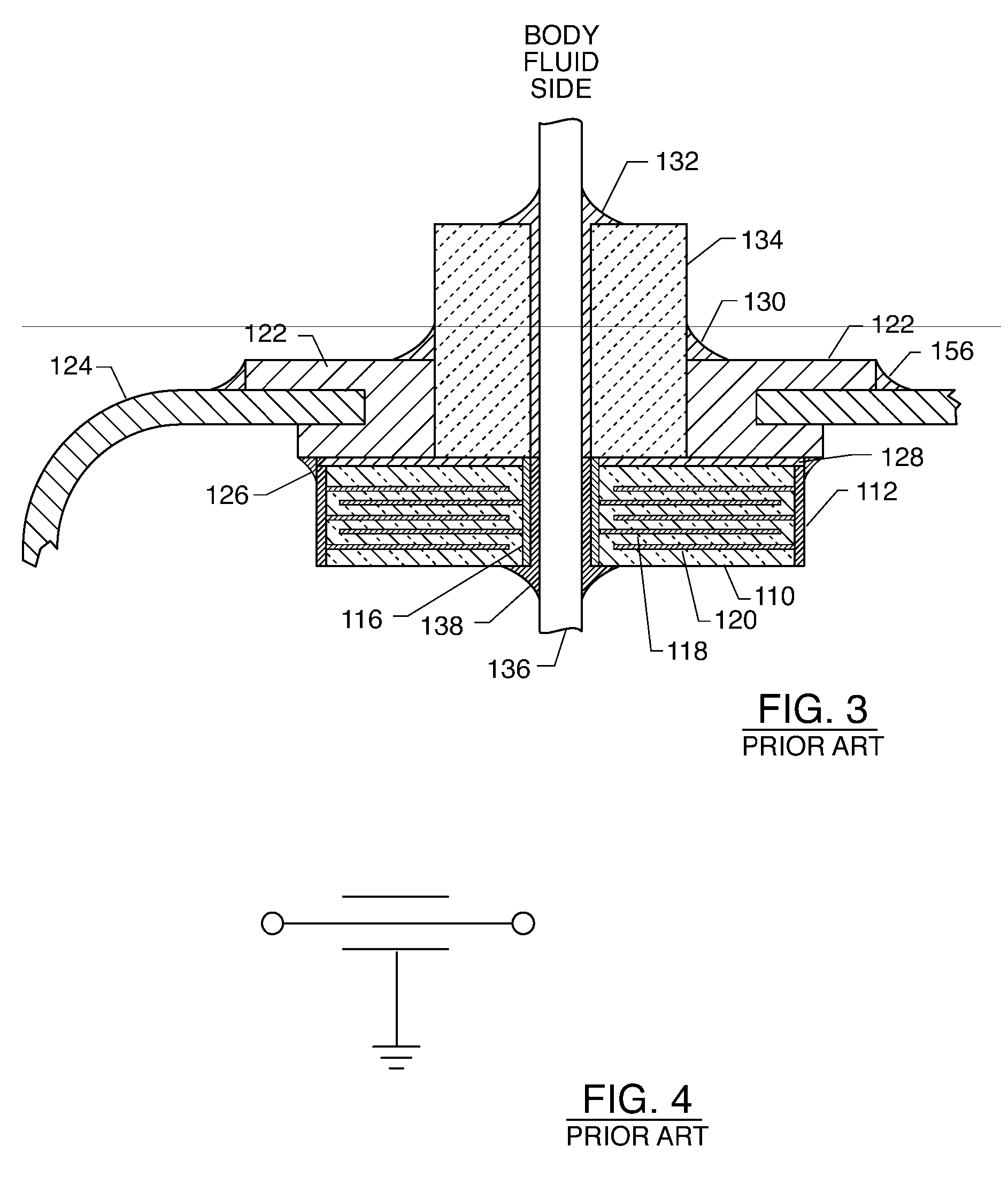
However, in the case where the terminal terminal pin 136 is of niobium, tantalum or titanium, solders and conductive adhesives generally cannot be applied directly to such pin materials.
However, during ultrasonic or thermal wire bonding, considerable energy is imparted into the structure, which can damage the structure, and particularly the ceramic capacitor.
It is generally not acceptable to have an opening or break in this lead wire anywhere in the system that would then be reattached during initial manufacturing with solder, conductive thermal setting adhesives or the like.

Method used


Image

  • Hermetic feedthrough terminal assembly with wire bond pads for human implant applications
  • Hermetic feedthrough terminal assembly with wire bond pads for human implant applications
  • Hermetic feedthrough terminal assembly with wire bond pads for human implant applications

Examples


Embodiment Construction

[0062] Reference will now be made in detail to presently preferred embodiments of the invention, examples of which are represented in the accompanying drawings for purposes of illustration. Such examples are provided by way of an explanation of the invention, not a limitation thereof. In fact, it will be apparent to those skilled in the art that various modifications and variations can be made in the present invention, without departing from the spirit and scope thereof. For instance, figures illustrated or described as part of one embodiment can be used on another embodiment to yield a still further embodiment. Still further, variations and selection of materials and / or characteristics may be practiced, to satisfy particular desired user criteria. Thus, it is intended that the present invention cover such modifications and variations as come within the scope of the present features and their equivalents. In the following description, functionally equivalent components of the variou...


PUM


Abstract

A feedthrough terminal assembly for active implantable medical devices includes a structural wire bond pad for a convenient attachment of wires from either the circuitry inside the implantable medical device or wires external to the device. Direct attachment of wire bond pads to terminal pins enables thermal or ultrasonic bonding of lead wires, while shielding the capacitor or other delicate components from the forces applied to the assembly during attachment of the wires.

Description

BACKGROUND OF THE INVENTION [0001] This invention relates generally to hermetic feedthrough terminal subassemblies and related methods of construction, particularly of the type used in active implantable medical devices such as cardiac pacemakers, implantable defibrillators, cochlear implants, neurostimulators, active drug pumps, and the like, and those incorporating an electromagnetic interference (EMI) filter designed to decouple and shield undesirable EMI signals from an associated device. More particularly, the present invention relates to an improved hermetic terminal that includes bonding pads for convenient attachment of lead wires by way of thermal or ultrasonic bonding, soldering or the like. The bonding pads can be attached to the capacitor structure or to a terminal pin. [0002] Feedthrough terminal assemblies are generally well known for connecting electrical signals through the housing or case of an electronic instrument. For example, in implantable medical devices, the ...

Claims


Application Information

Patent Timeline
Patent Type & Authority Applications(United States)
IPC IPC(8): A61N1/375
CPCH01G4/35A61N1/3754
Inventor STEVENSON, ROBERT A.BRENDEL, RICHARD L.FRYSZ, CHRISTINE A.HUSSEIN, HAYTHAMKNAPPEN, SCOTTSTEVENSON, RYAN A.
Owner WILSON GREATBATCH LTD
Why Eureka
Try Eureka