Eureka AIR delivers breakthrough ideas for toughest innovation challenges, trusted by R&D personnel around the world.

Method and apparatus for controlling a dc-transmission link

a technology of dc transmission link and control apparatus, which is applied in the direction of circuit arrangement, electric power transfer ac network, energy industry, etc., can solve the problems of system failure, voltage rise beyond safe limits, system failure, etc., and achieve the effect of simple construction and effective power generation

Inactive Publication Date: 2012-11-29
SIEMENS AG
View PDF39 Cites 51 Cited by
  • Summary
  • Abstract
  • Description
  • Claims
  • Application Information

AI Technical Summary

Benefits of technology

[0020]Further in particular, the control method may not require adjusting or changing a frequency at the power production unit side or the utility grid side of the DC transmission link. In particular, the frequency of the voltage at the AC-side at the AC-DC converter at the first side may be kept constant during the method. Further in particular, the frequency of the AC-side of the DC-AC converter, i.e. the second converter, of the DC-transmission link may be kept constant during performing the control method.
[0039]In particular, for decreasing AC voltage reference the torque may be reduced for reducing the power output of the wind turbine, thereby accelerating the rotational speed of the rotor shaft. Further, the rotor blade pitch angle may be changed in order to change or adapt an energy transfer from the wind to the rotor blade and thus to the rotor and thus finally to the generator. Other measures may be performed by the wind turbine converter or another control module of the wind turbine to reduce the power output of the wind turbine for decreasing AC voltage reference. In particular, a chopper to dissipate access energy may not be required. Thereby, an efficiency of the power production may be improved.

Problems solved by technology

The imbalance in the power may very quickly increase the level of the DC voltage in the HVDC transmission line, because the capacitors in the transmission system (converter capacitors and the cable capacitors) may be the only available energy storage devices.
If the imbalance in power is too big, it takes no time for the DC side voltage to rise beyond safe limits and the system to trip off.
Subsequently, the LV FRT (low-voltage fault-ride-through) requirements are not met.
When energy imbalance between the two end-converters occur (due to faults in the grid), the DC link voltage starts to rise.

Method used


Image

  • Method and apparatus for controlling a dc-transmission link
  • Method and apparatus for controlling a dc-transmission link
  • Method and apparatus for controlling a dc-transmission link

Examples


Embodiment Construction

[0055]The illustration in the drawings is in schematic form.

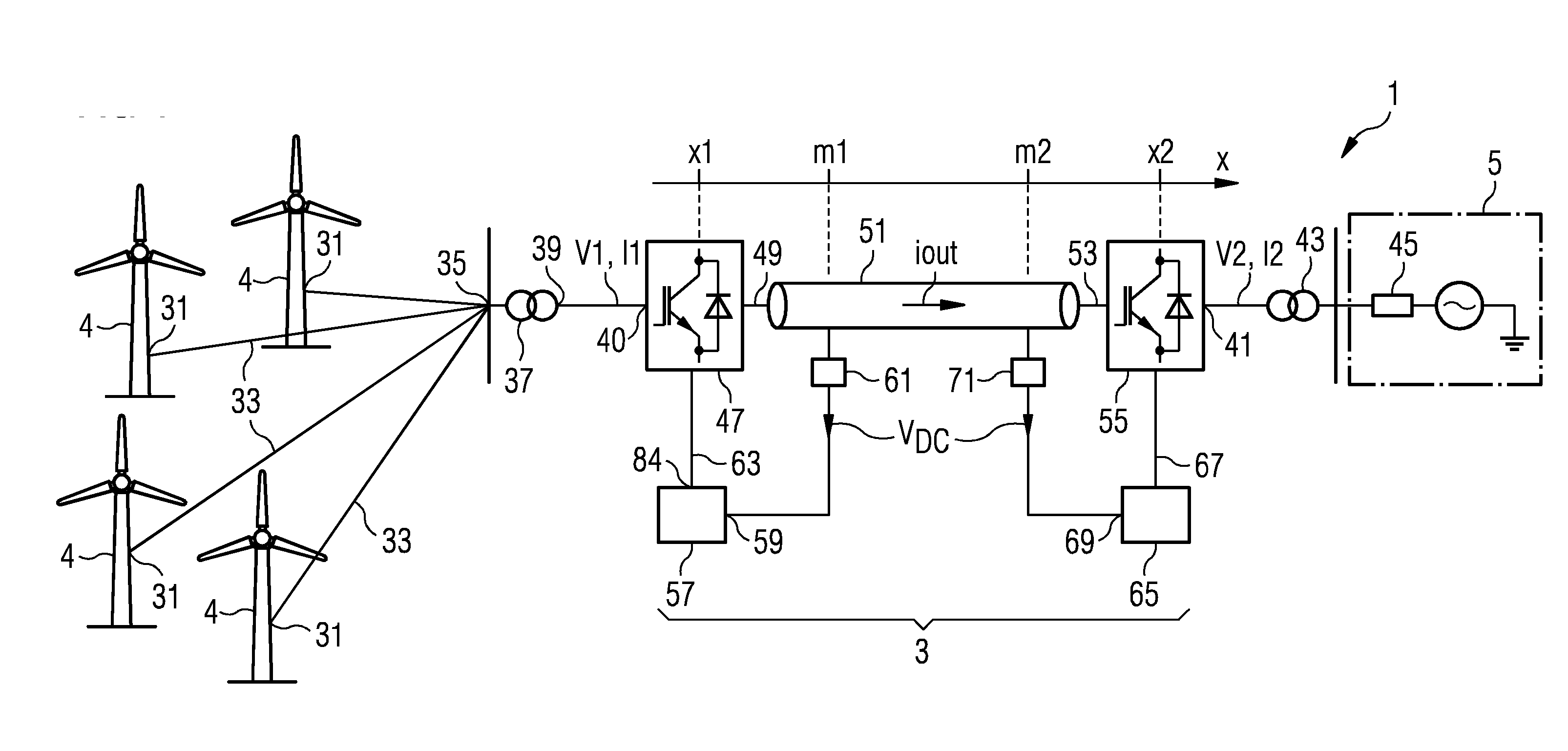
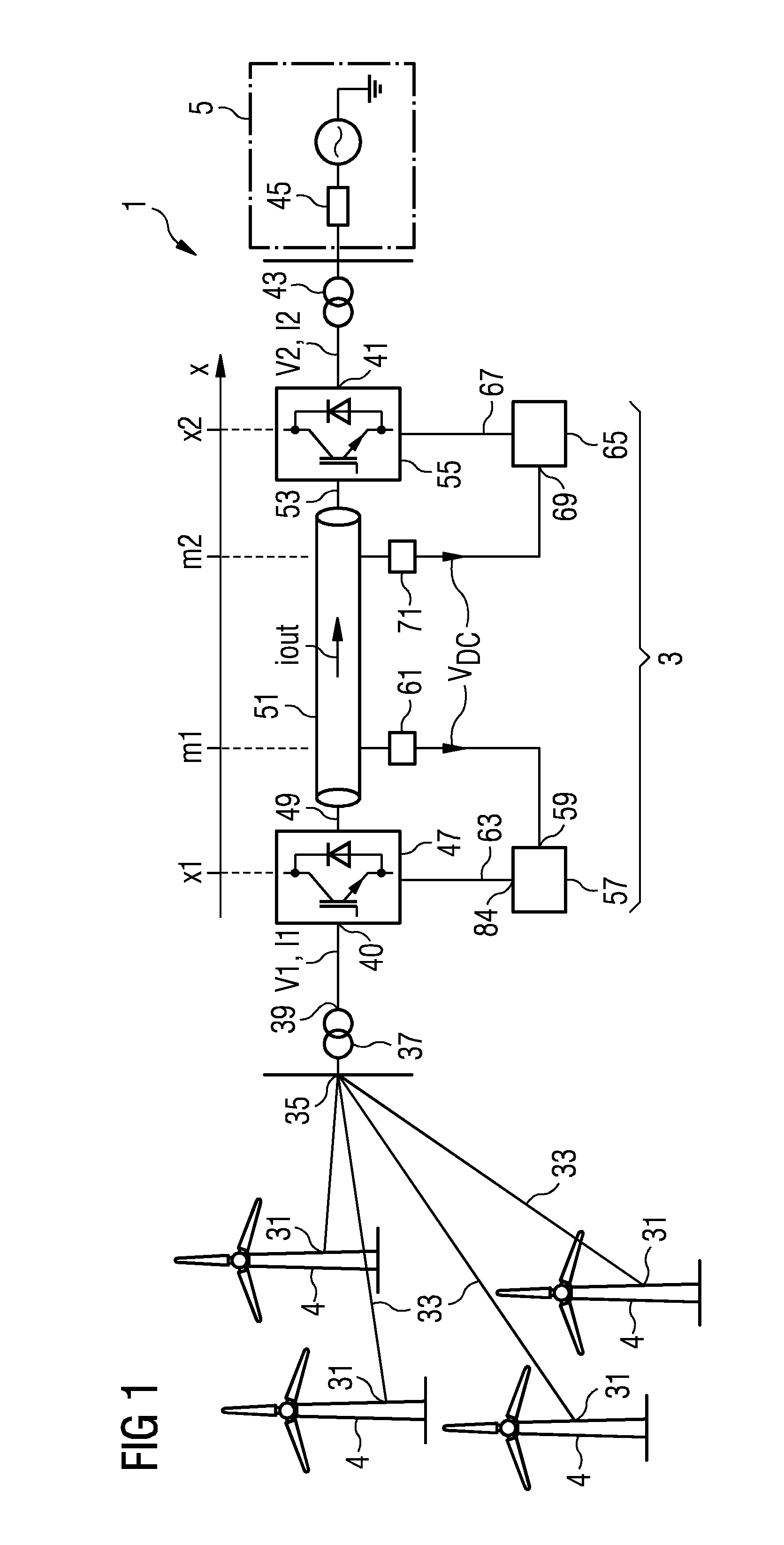
[0056]FIG. 1 schematically illustrates a power production facility 1, wherein electric energy generated by a plurality of wind turbines 4 is transmitted via a DC-transmission link 3 to a utility grid 5.

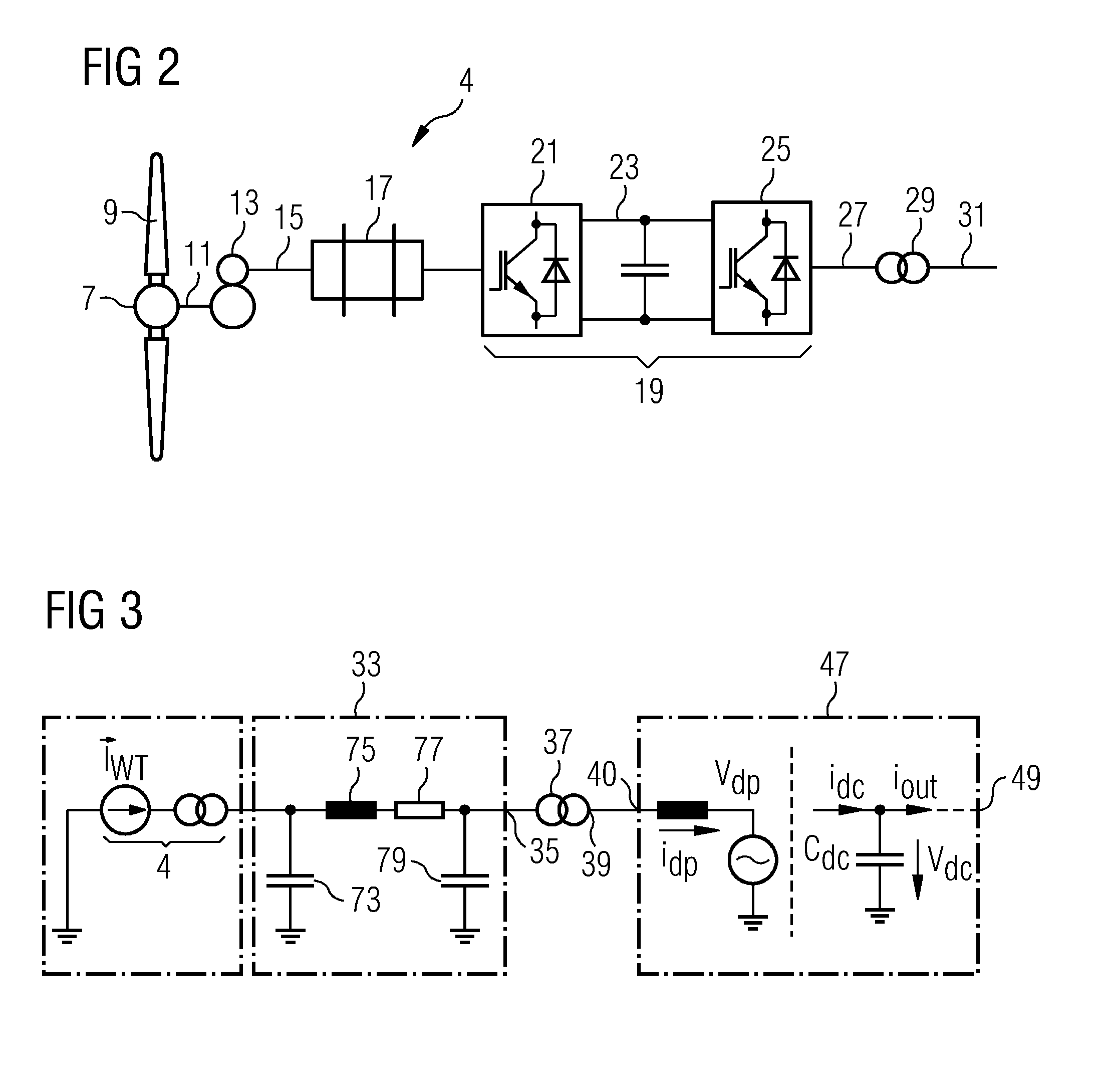
[0057]A wind turbine 4 schematically illustrated in FIG. 1 is depicted in further detail in FIG. 2. The wind turbine comprises a hub 7 to which two or more rotor blades 9 are connected. The hub is mechanically connected to a rotor shaft 11 which is mechanically connected to a gearbox 13. The gearbox 13 is adapted for adjusting a primary rotational speed with which the rotation shaft 11 rotates to a secondary rotational speed with which the secondary shaft 15 rotates. The secondary shaft 15 is mechanically connected to an electric generator 17 which is in the illustrated example an induction generator. The induction generator 17 outputs upon rotation of the secondary rotation shaft 15 a variable frequency AC-voltage which is s...


PUM


Abstract

A method for controlling a DC-transmission link for transmitting electric power from a power production unit connected to an AC-DC converter at a first side of the DC-transmission link to a utility grid connected to a DC-AC converter at a second side of the DC-transmission link is provided. The method includes: obtaining a DC voltage signal indicative of a DC voltage at the DC transmission link; controlling the AC-DC converter such that an AC voltage at an AC side of the AC-DC converter is adjusted based on the DC voltage signal. Further, an apparatus for controlling a DC-transmission link is provided.

Description

CROSS REFERENCE TO RELATED APPLICATIONS[0001]This application claims priority of European Patent Office Application No. 11167439.6 EP filed May 25, 2011. All of the applications are incorporated by reference herein in their entirety.FIELD OF INVENTION[0002]The present invention relates to a method and to an apparatus for controlling a DC-transmission link for transmitting electric power from a power production unit, in particular a wind turbine, connected to an AC-DC converter at a first side of the DC-transmission link to a utility grid connected to a DC-AC converter at a second side of the DC-transmission link.ART BACKGROUND[0003]Electric energy produced in a wind farm or a wind park needs to be transmitted to a utility grid to which one or more consumers are connected to be supplied with electric energy.[0004]Power from an offshore wind power plant may be transmitted to the nearby on-land transmission system via a HVAC (high voltage alternating current) or a HVDC (high voltage di...

Claims


Application Information

Patent Timeline
IPC IPC(8): H02J3/36
CPCH02J3/36Y02E60/60H02J3/386Y02E10/763H02J2300/28H02J3/381Y02E10/76Y02P80/10
Inventor JENSEN, KIM HOEJSHARMA, RANJAN
Owner SIEMENS AG
Why Eureka
Eureka Blog
Learn More