Peristaltic hose pump

a hose pump and peristaltic technology, applied in the direction of flexible member pumps, machines/engines, positive displacement liquid engines, etc., can solve the problems of premature reduction of resetting forces, increased electrical energy consumption, and negative influence of sealing diaphragm arrangement in this manner

Inactive Publication Date: 2007-05-15
B BRAUN MELSUNGEN AG
View PDF14 Cites 42 Cited by
  • Summary
  • Abstract
  • Description
  • Claims
  • Application Information

AI Technical Summary

Benefits of technology

[0003]Peristaltic hose pumps are often used as infusion or transfusion pumps for conveying liquid substances in the medical field. Linear hose pumps are known wherein numerous pump fingers continuously and cyclically press a straight pump hose against an abutment so that the liquid in the pump hose is moved in the direction of delivery. European Patent Application 0 214 443 A1 describes a peristaltic linear hose pump with numerous eccentric discs fastened to a shaft. Each eccentric disc carries a ball bearing and acts upon a linearly movable pump finger. All the pump fingers are spanned by a sealing diaphragm forming a sealing separation between the drive mechanism and the pump hose. Thereby, damage and contaminations of the pump hose are avoided. On the other hand, the interior of the pump is protected against intruding liquid. A sealing diaphragm arranged in this manner has a negative influence upon the delivery accuracy. It causes a coupling of forces between neighboring pump fingers, whereby the consumption of electrical energy is increased as well. With the diaphragm disposed in this manner, a share of the resetting forces of the pump hose is used to deform the sealing diaphragm against the pump fingers. This may lead to a premature decrease of the resetting forces. Infusion pumps such as peristaltic hose pumps, for example, shall be built to be as small and light-weighted as possible. Therefore, it is important to reduce the requirement of energy in order to dimension components such as accumulator, power pack and drive motor as small as possible. At the same time, the demand to keep to the chosen rate of delivery has to be satisfied, even during long infusion times.
[0017]The invention prevents disturbing influences of the sealing diaphragm upon the delivery accuracy. Also, the sealing diaphragm is not fulled and not squeezed between pump fingers and pump hose.
[0018]According to a preferred embodiment of the invention, it is provided that the sealing diaphragm has folds at both sides of the pump hose, which permit an adaptation to the transverse movements of the connecting rod.
[0019]Preferably, a guide plate with a longitudinally extending receiving channel for the pump hose and with guide channels for the pump fingers is provided at the side of the pump hose. Suitably, this guide plate is removable for cleaning purposes.

Problems solved by technology

A sealing diaphragm arranged in this manner has a negative influence upon the delivery accuracy.
It causes a coupling of forces between neighboring pump fingers, whereby the consumption of electrical energy is increased as well.
This may lead to a premature decrease of the resetting forces.

Method used


Image

  • Peristaltic hose pump
  • Peristaltic hose pump
  • Peristaltic hose pump

Examples


Embodiment Construction

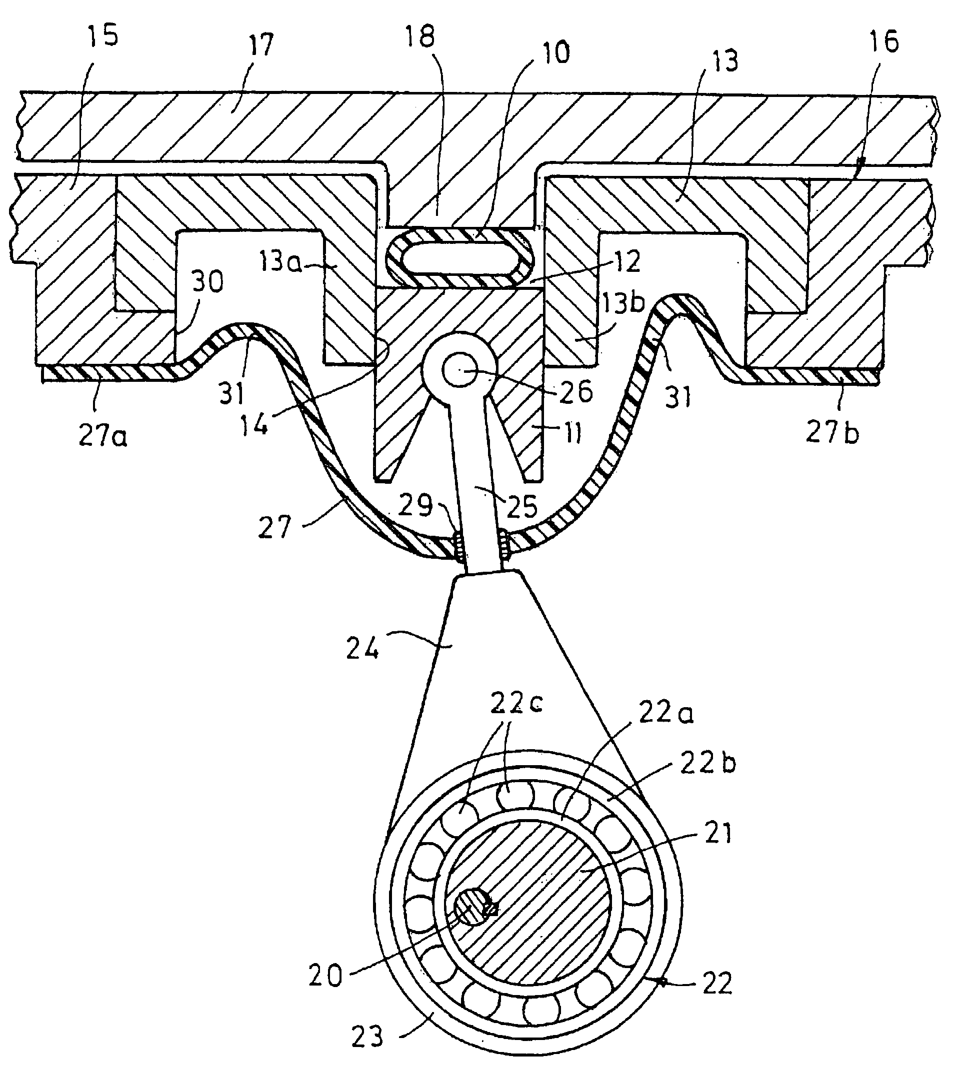
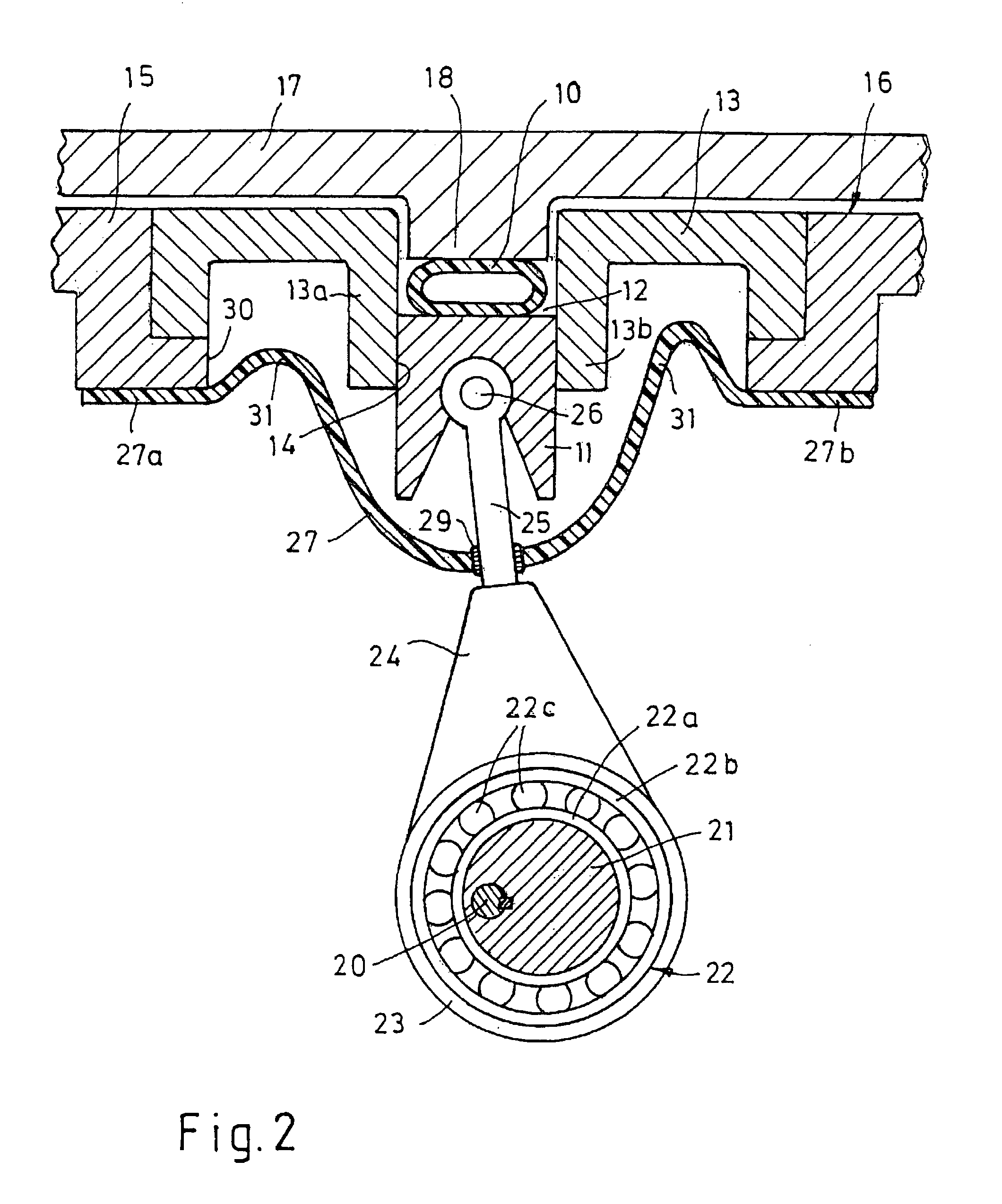
[0007]Referring to FIGS. 1 and 2, the illustrated hose pump comprises a pump hose 10 in which the liquid to be pumped is located. This pump hose 10 is continuously periodically compressed and relieved by numerous pump fingers 11, as described in European Patent 0 214 443.

[0008]The pump hose 10 is included in a receiving channel 12 formed in a guide plate 13. The guide plate 13 has parallel walls 13a and 13b laterally defining the receiving channel 12. The receiving channel 12 is connected with several guide channels 14 in each of which a pump finger 11 is guided transversely to the hose direction. The guide plate 13 is mounted to a front wall 15 of a pump housing 16. The pump housing has a door attached in front that forms a thrust bearing 17 for supporting the pump hose 10. The thrust bearing 17 has a projection 18 projecting into the receiving channel 12.

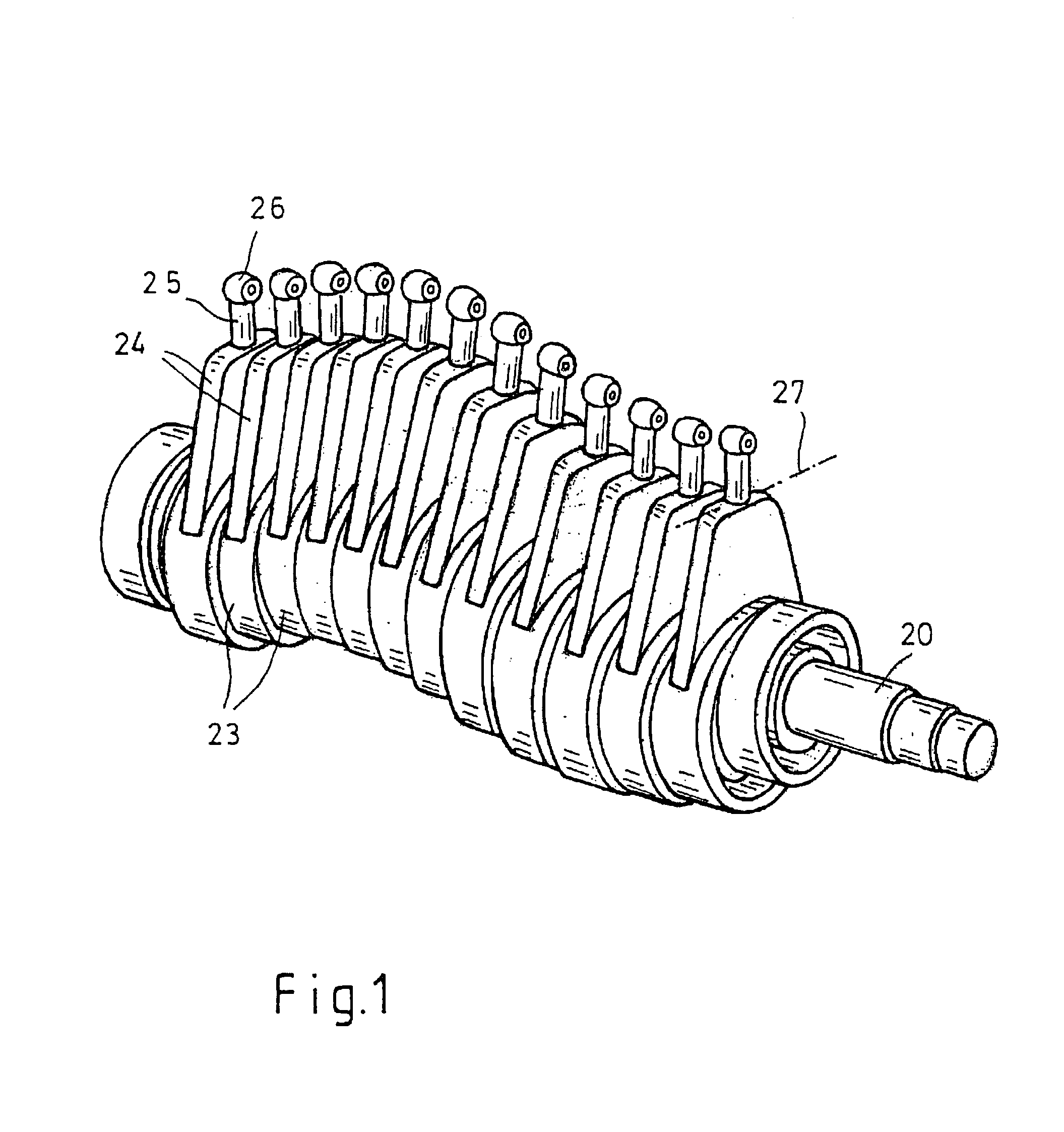
[0009]There are about twelve pump fingers 11 altogether, which are driven by an eccentric drive in a sinusoidal manner; accordin...


PUM


Abstract

The hose pump comprises an eccentric drive with numerous eccentric discs (21) fastened to a shaft (20). Each eccentric disc (21) drives a crank drive (24) having a connecting rod (25). At the end of the connecting rod (25), a pump finger (11) is borne for compressing a pump hose (10). A sealing diaphragm (27) is disposed between the eccentric drive and the pump hose (10) for preventing liquid from intruding into the interior of the housing (16). The connecting rod (25) sealingly passes through the sealing diaphragm (27). The sealing diaphragm (27) comprises lateral folds (31) so that it does not exert any substantial forces upon the crank drive (24). The hose pump has a low power consumption and permits a small structure.

Description

RELATED APPLICATIONS[0001]This application claims priority from German Utility Model Application No. 202 10 502.4, filed on Jul. 6, 2002, incorporated herein by reference for all legitimate purposes and relied upon for priority.FIELD OF INVENTION[0002]The invention relates to a peristaltic hose pump with a shaft comprising several eccentric discs each of which carries a bearing and thus moves a pump finger transversely to a pump hose, and with a sealing diaphragm disposed between the shaft and the pump hose.DESCRIPTION OF RELATED ART[0003]Peristaltic hose pumps are often used as infusion or transfusion pumps for conveying liquid substances in the medical field. Linear hose pumps are known wherein numerous pump fingers continuously and cyclically press a straight pump hose against an abutment so that the liquid in the pump hose is moved in the direction of delivery. European Patent Application 0 214 443 A1 describes a peristaltic linear hose pump with numerous eccentric discs fastene...

Claims


Application Information

Patent Timeline
Patent Type & Authority Patents(United States)
IPC IPC(8): F04B45/06F04B43/08F04B43/12
CPCF04B43/082
Inventor HERWIG, DIETERKNUTH, REINHARD
Owner B BRAUN MELSUNGEN AG
Why Eureka
Try Eureka