Unlock instant, AI-driven research and patent intelligence for your innovation.

True RMS vibration intensity two wire transmitter

A technology of vibration intensity and true effective value, applied in instruments, measuring devices, measuring ultrasonic/sonic/infrasonic waves, etc., can solve the problems of low basic power consumption, complex circuits, and application errors of two-wire transmitters, and achieve low cost , basic power consumption is small, the effect of accurate conversion

Inactive Publication Date: 2013-07-03
CHENGDU SAITENG AUTOMATION ENG
View PDF5 Cites 0 Cited by
  • Summary
  • Abstract
  • Description
  • Claims
  • Application Information

AI Technical Summary

Problems solved by technology

[0004] In actual use, the vibrating two-wire transmitter is not as effective as the two-wire transmitters such as temperature and pressure. The main problem is that the power supply of the two-wire transmitter itself is two wires shared with the 4-20mA current loop circuit. , which determines that the basic power consumption of the two-wire transmitter must be small, and the basic current to maintain its own operation must be less than 4mA
[0006] 1. When the vibration signal is an alternating signal with a complex waveform, it may be a sinusoidal waveform of a single frequency, or a complex waveform containing multiple frequency components. To obtain the real effective value of these signals, a relatively complex circuit is necessary
[0007] 2. Due to the limitation of power supply characteristics, the two-wire transmitter brings a lot of difficulties to the design of the true effective value circuit. Therefore, many vibration intensity two-wire transmitters on the market do not reflect the true effective value of speed, but Some approximate processing has been done, causing large errors when applied under complex waveforms

Method used


Image

  • True RMS vibration intensity two wire transmitter
  • True RMS vibration intensity two wire transmitter
  • True RMS vibration intensity two wire transmitter

Examples


Embodiment Construction

[0020] The present invention will be further described in detail below with reference to the drawings and specific embodiments:

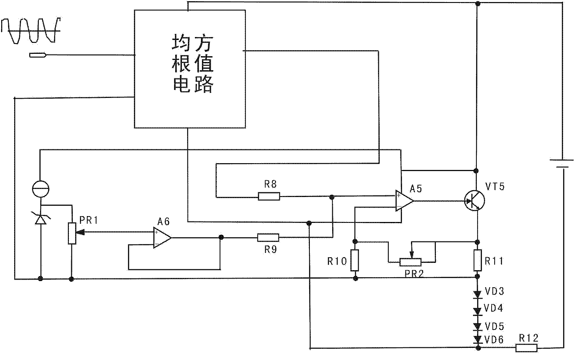
[0021] Such as figure 1 with figure 2 As shown, a true effective value vibration intensity two-wire transmitter of the present invention has a circuit including an amplifier circuit and a root mean square value conversion circuit. The signal input end of the root mean square value conversion circuit and the signal output of the vibration velocity sensor Terminal is connected, the vibration velocity sensor outputs a voltage waveform reflecting the vibration velocity, which is input into the root mean square value conversion circuit and converted into an equivalent DC voltage output signal; the signal output terminal of the root mean square value conversion circuit is connected to the The signal input end of the amplifying circuit is connected, and the amplifying circuit appropriately amplifies the DC voltage signal output by the root mean square circuit...


PUM


Abstract

The invention discloses a true RMS vibration intensity two wire transmitter. A circuit comprises: an amplification circuit and a root mean square value converting circuit. The root mean square value circuit comprises: an absolute value circuit, a power division circuit and a filtering circuit. A signal input terminal of the absolute value circuit is connected with a signal output terminal of a vibration speed sensor. The signal output terminal of the absolute value circuit is connected with the signal input terminal of the power division circuit. The signal output terminal of the power division circuit is connected with the signal input terminal of the filtering circuit. The signal output terminal of the filtering circuit is connected with the signal input terminal of the amplification circuit. The circuit of the invention is simple, and under a low power consumption requirement, accuracy conversion of the true RMS of a complex alternating signal can be realized.

Description

Technical field [0001] The invention relates to a transmitter, in particular to a true effective value vibration intensity two-wire transmitter, belonging to the field of electrical automation. Background technique [0002] There are various machinery and equipment on the industrial site. In order to ensure the long-term stable and reliable operation of these equipment, a lot of condition monitoring instruments are needed to monitor the key parts of these equipment in real time. At the same time, the measurement data of various monitoring instruments needs to be shared with the control center system. Using 4-20mA current or 0-10V, 1-5V voltage is currently the most common way of monitoring data sharing in industrial sites. In computer automatic measurement and control systems, changes in various physical quantities such as temperature, pressure, and flow are usually converted into 4-20mA current signals that conform to industry standards. With the development of microcontroller...

Claims


Application Information

Patent Timeline
Patent Type & Authority Patents(China)
IPC IPC(8): G01H11/06
Inventor 杨川
Owner CHENGDU SAITENG AUTOMATION ENG