Device used for preventing flue gas at outlet of chimney from carrying droplets after wet desulphurization

A technology of chimney outlet and wet desulfurization, which is applied to exhaust gas devices, combustion methods, and treatment of combustion products, can solve the problems of increasing pollutant emissions, affecting the safety of chimneys, and insufficient design understanding, so as to achieve good social benefits and Economic benefits, reduced cleaning and maintenance workload, and the effect of avoiding droplet carrying phenomenon

Active Publication Date: 2012-07-11
CENT SOUTHERN CHINA ELECTRIC POWER DESIGN INST CHINA POWER ENG CONSULTING GROUP CORP
View PDF8 Cites 3 Cited by
  • Summary
  • Abstract
  • Description
  • Claims
  • Application Information

AI Technical Summary

Problems solved by technology

A large number of domestic coal-fired power plants equipped with wet desulfurization devices are not equipped with GGH devices. Due to insufficient understanding of the design of "wet chimneys", the phenomenon of liquid droplet carry-over at the outlet of "wet chimneys" is very common in China, that is, the flue gas at the chimney outlet carries Droplets, because the droplets contain dust, gypsum particles, and acidic substances, etc., will have a greater adverse impact on the power plant and the surrounding environment, causing environmental harm to the surroundings of the chimney, which essentially increases the discharge of related pollutants; at the same time , if the corrosive droplets flow to the outer wall of the chimney without anticorrosion, it will cause corrosion and damage to the outer surface, and also affect the safety of the chimney

Method used


Image

  • Device used for preventing flue gas at outlet of chimney from carrying droplets after wet desulphurization
  • Device used for preventing flue gas at outlet of chimney from carrying droplets after wet desulphurization
  • Device used for preventing flue gas at outlet of chimney from carrying droplets after wet desulphurization

Examples


Embodiment Construction

[0025] The present invention will be further described in detail below in conjunction with the accompanying drawings and specific embodiments.

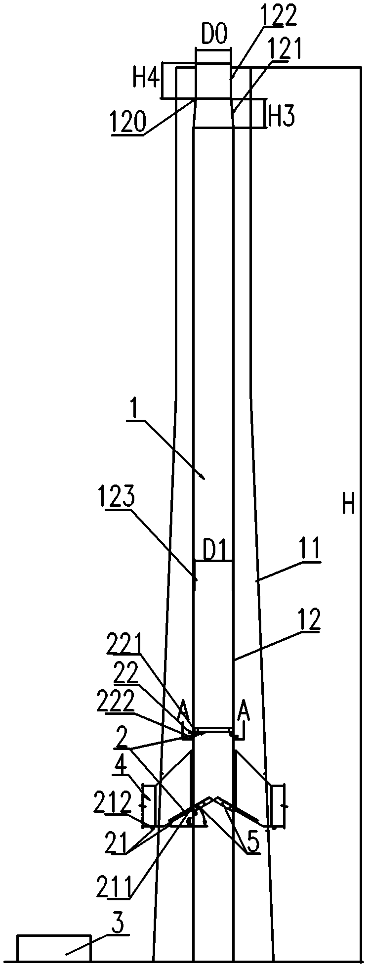
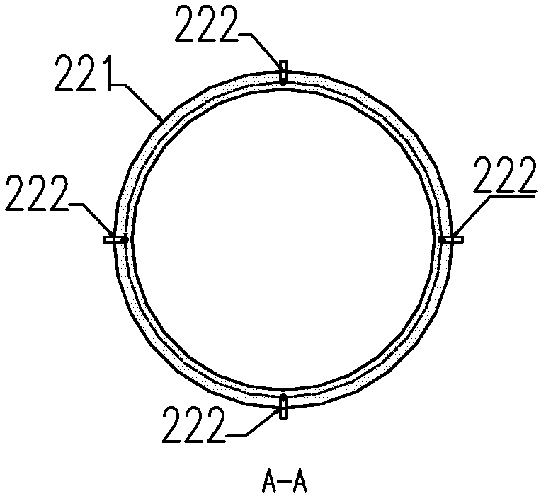
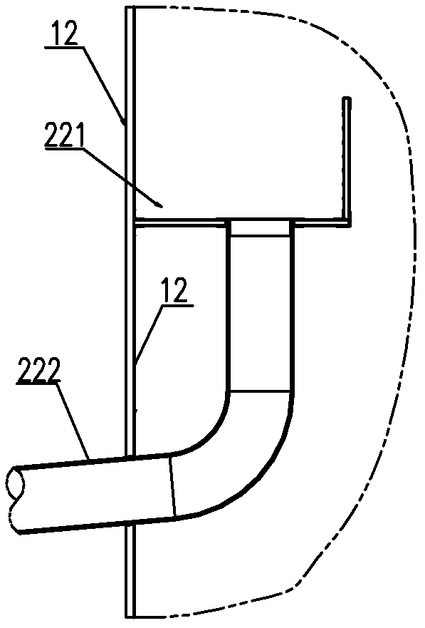
[0026] The anti-flue gas droplet carrying device at the chimney outlet after wet desulfurization shown in the figure includes a casing chimney 1 and a main flue 4. The casing chimney 1 includes a chimney outer cylinder 11 and a chimney inner cylinder 12. In the casing chimney 1 A droplet recovery device 2 is provided inside. The droplet recovery device 2 includes a first-stage acid liquid discharge device 21 and a second-stage acid liquid discharge device 22 . An anti-clogging cleaning device 5 is also provided under the droplet recovery device 2 .

[0027] The chimney inner cylinder 12 is sleeved in the chimney outer cylinder 11, the chimney inner cylinder 12 includes an outlet section 120 and a lower smoke exhaust pipe 123, the outlet section 120 includes an outlet contraction section 121 and an outlet straight section 122, and the d...


PUM


Abstract

The invention discloses a device used for preventing flue gas at an outlet of a chimney from carrying droplets after wet desulphurization, which comprises the sleeve chimney and a main chimney flue. The device is characterized in that the sleeve chimney consists of an outer chimney barrel and an inner chimney barrel, a droplet recycling device is disposed inside the sleeve chimney and consists of a primary acid liquid draining device and a secondary acid liquid draining device, and a blockage-preventive cleaning device is further arranged below the droplet recycling device. By the aid of the reasonable scheme of the cylindrical inner barrel of the sleeve chimney and designs of the droplet recycling device and the blockage-preventive cleaning device, the problem that flue gas at an outlet of an existing chimney carries droplet is solved. The device can effectively prevent the droplets from being carried, conditions of a power plant and surrounding environment conditions of the power plant can be greatly improved by means of popularizing the technical scheme of the device, cleaning and maintaining workload is reduced, and excellent social benefit and economic benefit can be obtained.

Description

technical field [0001] The invention relates to the flue gas treatment of a coal-fired thermal power plant in the electric power industry, in particular to a flue gas droplet carrying device at the outlet of a chimney after wet desulfurization. Background technique [0002] At present, the desulfurization process of new domestic coal-fired power plants generally adopts the limestone / gypsum process, and is not equipped with GGH (flue gas-flue gas heat exchanger). At this time, the flue gas entering the chimney is saturated flue gas, and the chimney configured is called "conventional Wet chimney". A large number of domestic coal-fired power plants equipped with wet desulfurization devices are not equipped with GGH devices. Due to insufficient understanding of the design of "wet chimneys", the phenomenon of liquid droplet carry-over at the outlet of "wet chimneys" is very common in China, that is, the flue gas at the chimney outlet carries Droplets, because the droplets contai...

Claims


Application Information

Patent Timeline
Patent Type & Authority Applications(China)
IPC IPC(8): F23J11/00F23J13/00
Inventor 陈牧田庆峰郭建张习强贾燕陈佳乐
Owner CENT SOUTHERN CHINA ELECTRIC POWER DESIGN INST CHINA POWER ENG CONSULTING GROUP CORP
Why Eureka
Try Eureka