Resonant switching circuit

A technology of resonant conversion and resonant inductance, applied in the field of power supply, can solve problems such as uneven current of resonant conversion circuit units

Inactive Publication Date: 2012-07-25
HUAWEI TECH CO LTD
View PDF7 Cites 44 Cited by
  • Summary
  • Abstract
  • Description
  • Claims
  • Application Information

AI Technical Summary

Problems solved by technology

[0005] In view of this, an embodiment of the present invention provides a resonant conversion circuit, which aims to solve t

Method used


Image

  • Resonant switching circuit
  • Resonant switching circuit
  • Resonant switching circuit

Examples


Embodiment Construction

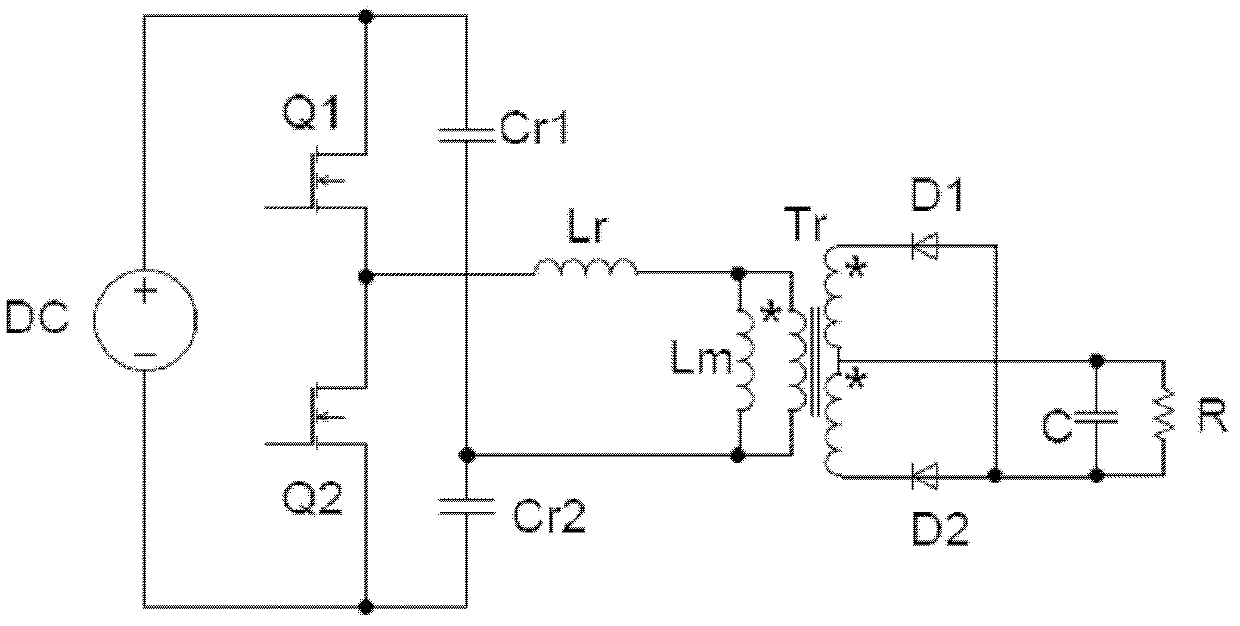
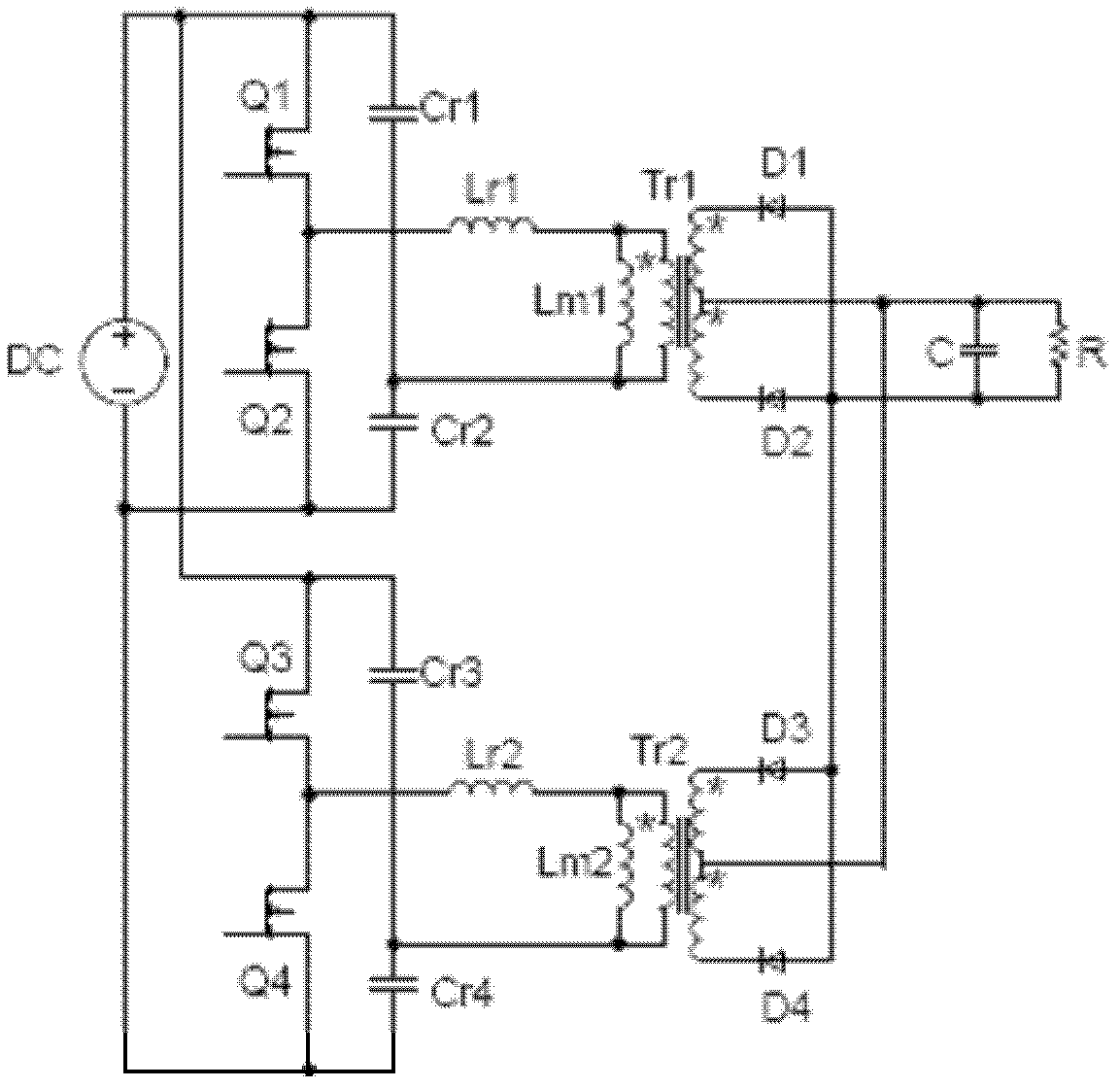
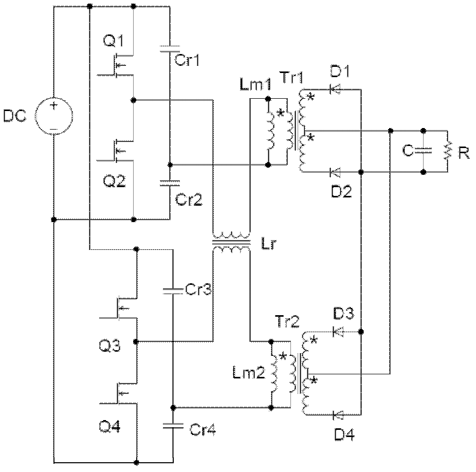
[0020] The embodiment of the present invention discloses a resonant conversion circuit. By integrating the magnetic devices in the resonant conversion circuit unit of two-phase or multi-phase interleaving and parallel connection on the same magnetic core, the magnetic circuit coupling effect is used to realize the resonant conversion of different phases. The current sharing of the circuit unit solves the problem of uneven current sharing of the resonance conversion circuit units of each phase in the existing resonance conversion circuit.

[0021] The following will clearly and completely describe the technical solutions in the embodiments of the present invention with reference to the accompanying drawings in the embodiments of the present invention. Obviously, the described embodiments are only some, not all, embodiments of the present invention. Based on the embodiments of the present invention, all other embodiments obtained by persons of ordinary skill in the art without ma...


PUM


Abstract

The embodiment of the invention provides a resonant switching circuit. The resonant switching circuit comprises at least two resonant switching circuit units, wherein the resonant switching circuit units are staggered and connected in parallel, and magnetic devices in the resonant switching circuit units are alternately and magnetically integrated on the same magnetic core. As the magnetic devices integrated on the same magnetic core can exert a magnetic path coupling effect, a self current-balancing effect can be produced by currents on circuit branches of different phases, so that the current balance of the resonant switching circuit units in the resonant switching circuit is realized, and the volume of a power supply is reduced due to the integration of the magnetic devices.

Description

technical field [0001] The invention relates to the field of power supplies, in particular to a resonant conversion circuit. Background technique [0002] The resonant conversion circuit has the advantage of high conversion efficiency, so it is used more and more. The typical LLC symmetrical half-bridge resonant conversion circuit unit is as follows: figure 1 As shown, including switching devices Q1, Q2, resonant inductance Lr, excitation inductance Lm of transformer Tr, resonant capacitors Cr1, Cr2, rectifier devices D1, D2, this resonant conversion circuit is connected to a DC power supply, and the power energy is transferred to The secondary side is supplied to the load R after being filtered by the filter capacitor C. [0003] Although the resonant conversion circuit can obtain high conversion efficiency, the ripple current passing through the filter capacitor C is easy to exceed the standard when the output power is high. power supply, for example, such as figure 2 ...

Claims


Application Information

Patent Timeline
IPC IPC(8): H02M3/335H02M1/14
CPCH02M1/00H02M3/33507H02M1/14H02M2001/0058H01F30/06H02M3/285Y02B70/1433H01F27/24H02M3/335H01F30/10Y02B70/10H02M1/0058H02M1/0043
Inventor 徐金柱潘灯海
Owner HUAWEI TECH CO LTD
Why Eureka
Try Eureka