SCR (Selective Catalytic Reduction) denitrification, anti-blocking and effect-increasing system

An anti-blocking and denitrification technology, applied in the field of SCR denitrification system, can solve the problems of increased operating costs, uneven distribution, and increased escape volume of the system, and achieve the effect of reducing the problem of ash accumulation, reducing ash blocking and covering a large area.

Pending Publication Date: 2018-11-13
SHANGHAI UNIVERSITY OF ELECTRIC POWER
View PDF7 Cites 2 Cited by
  • Summary
  • Abstract
  • Description
  • Claims
  • Application Information

AI Technical Summary

Problems solved by technology

However, with the change of boiler load and the adjustment of equipment operating status, the distribution of ammonia-nitrogen ratio at the catalyst gradually becomes uneven, and the NH 3 The amount of escape increased again, and NH could not be solved fundamentally 3 escape problem
[0004] In order to clean the soot accumulation of the SCR denitrification system in engineering, more sootblowers will be needed to perform sootblowing more frequently, which will increase the cost of system operation

Method used


Image

  • SCR (Selective Catalytic Reduction) denitrification, anti-blocking and effect-increasing system
  • SCR (Selective Catalytic Reduction) denitrification, anti-blocking and effect-increasing system
  • SCR (Selective Catalytic Reduction) denitrification, anti-blocking and effect-increasing system

Examples


Embodiment

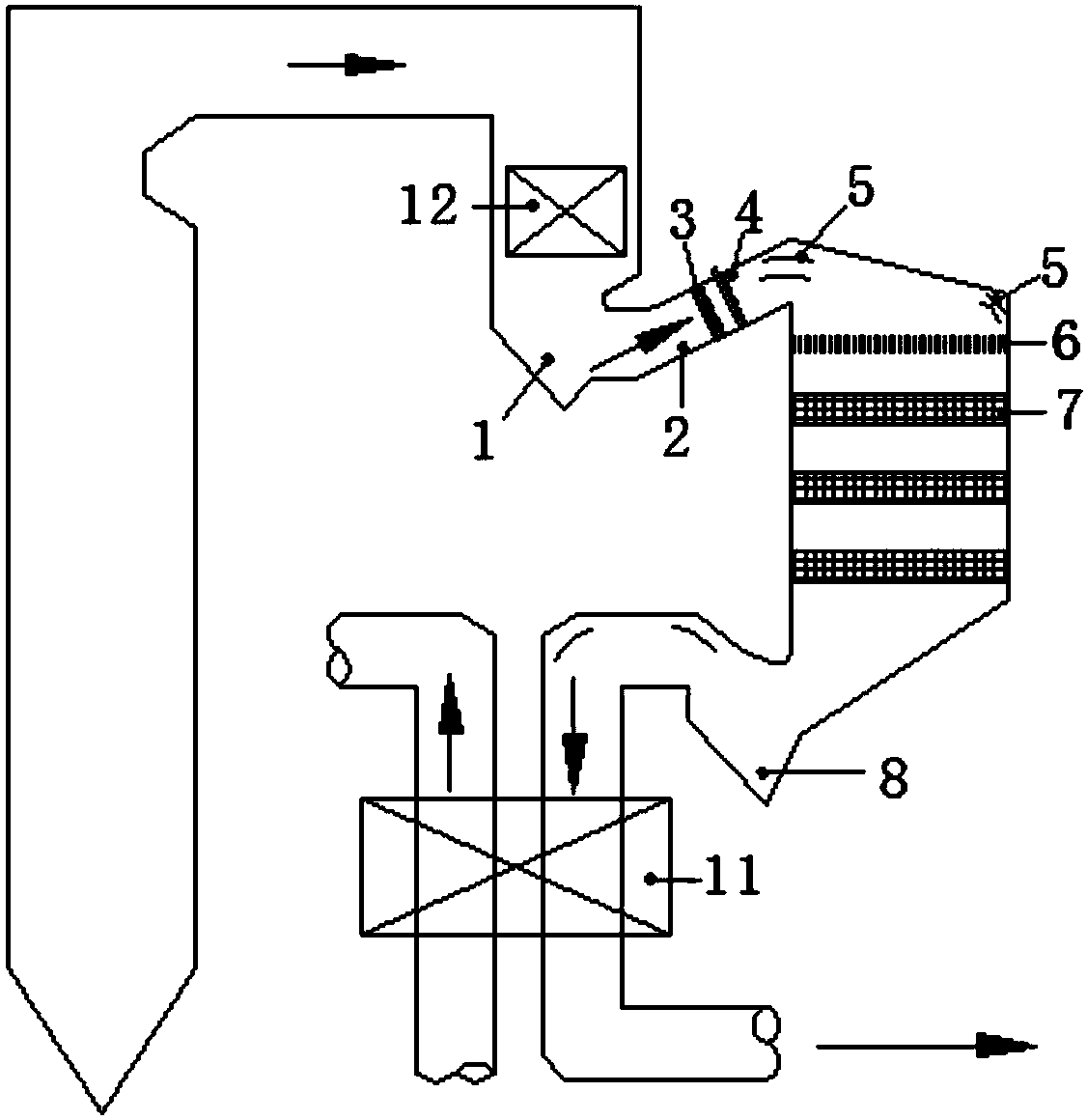
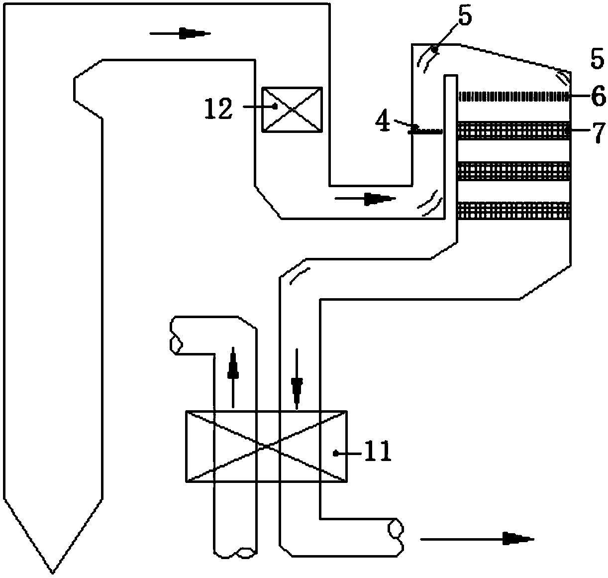
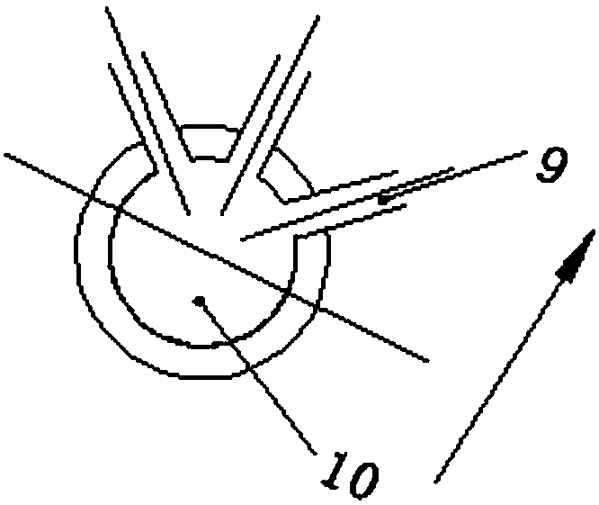
[0029] Existing SCR denitrification systems such as figure 2 As shown, the ammonia injection grid 4 is arranged horizontally in the conventional SCR denitrification system. Since the flue is arranged vertically, the ammonia injection direction of the ammonia injection grid 4 is the same as that of the flue gas flow. Refer to Figure 4 Generally, the nozzle adopts a single nozzle and is arranged vertically upward. A large amount of fly ash carried in the flue gas will fall into the nozzle due to gravity, thereby blocking the nozzle and seriously affecting the uniformity of ammonia nitrogen. In addition, when the flue gas flow carrying a large amount of fly ash passes through the SCR denitration catalyst layer 7 from top to bottom, the fly ash promotes ash intake and ash deposition in the SCR denitration catalyst layer 7 under the action of gravity.

[0030] This embodiment proposes an SCR denitrification anti-blocking efficiency improvement system, including an inlet flue, an ...


PUM


Abstract

The invention relates to an SCR (Selective Catalytic Reduction) denitrification, anti-blocking and effect-increasing system. The SCR denitrification, anti-blocking and effect-increasing system comprises an inlet flue, an SCR denitrification reactor and an outlet flue, which are arranged in sequence along a flowing direction of flue gas, wherein the inlet flue is connected with an outlet channel ofa coal economizer; the outlet flue is connected with an inlet channel of an air pre-heater; the inlet channel comprises a primary dust removal section and a secondary dust removal section; the primary dust removal section is internally provided with an inlet ash bucket connected with the outlet channel of the coal economizer; the secondary dust removal section is an inclined flue and the bottom end of the inclined flue is connected with the inlet ash bucket and the inclined flue is inclined upward along a flue gas flowing direction; the inclined flue is internally provided with an air flow distribution plate and an ammonia spraying grid in sequence along the flue gas flowing direction; the ash outlet channel is internally provided with an outlet ash bucket. Compared with the prior art, ash blocking of an SCR denitrification system is reduced and the ammonia and nitrogen mixing degree is increased; the problems of ash deposition of an SCR denitrification catalyst layer and high pressure difference of the air pre-heater are greatly alleviated, and energy-saving and efficient operation of the SCR denitrification system is ensured.

Description

technical field [0001] The invention relates to an SCR denitrification system, in particular to an SCR denitrification anti-blocking and efficiency-improving system. Background technique [0002] Selective Catalytic Reduction (SCR) is a high-efficiency NOx control technology commonly used in coal-fired power plant boilers, and most of them adopt high-dust arrangements, that is, SCR is located in the economizer and air preheater (air preheater for short) )between. Due to the long-term high-dust environment, the catalyst is easily blocked, worn and poisoned. In addition, the dust in the flue gas is also easy to block the ammonia injection port of the ammonia injection grid, which increases the non-uniformity of the flow rate of ammonia gas and the non-uniformity of the ammonia-nitrogen ratio at the catalyst inlet interface, which seriously affects the denitrification effect of the catalyst. NH 3 - The unevenness of NOx mixing tends to become more serious with the passage of...

Claims


Application Information

Patent Timeline
Patent Type & Authority Applications(China)
IPC IPC(8): B01D53/90B01D53/56B01D45/08B01D45/02
CPCB01D45/02B01D45/08B01D53/8631B01D53/90
Inventor 官贞珍郭瑞堂潘卫国李芳芹
Owner SHANGHAI UNIVERSITY OF ELECTRIC POWER
Why Eureka
Try Eureka