
3D scene cutting method based on scanning ray

A scanning ray and 3D technology, applied in the field of 3D scene clipping based on scanning ray, to achieve the effect of solving the problem of visibility judgment

Inactive Publication Date: 2014-07-30
FUJIAN TIANQU NETWORK TECH
View PDF3 Cites 0 Cited by
  • Summary
  • Abstract
  • Description
  • Claims
  • Application Information

AI Technical Summary

Problems solved by technology

[0004] The technical problem to be solved by the present invention is to provide a 3D scene clipping method based on scanning rays, which replaces the scene model with the ray detection body to perform fast ray scanning during the running period, effectively solves the problem of the visibility judgment of the scene model, and is not affected by 3D scene layout restrictions apply to most indoor and outdoor 3D scene management

Method used


Image

  • 3D scene cutting method based on scanning ray
  • 3D scene cutting method based on scanning ray
  • 3D scene cutting method based on scanning ray

Examples


Embodiment Construction

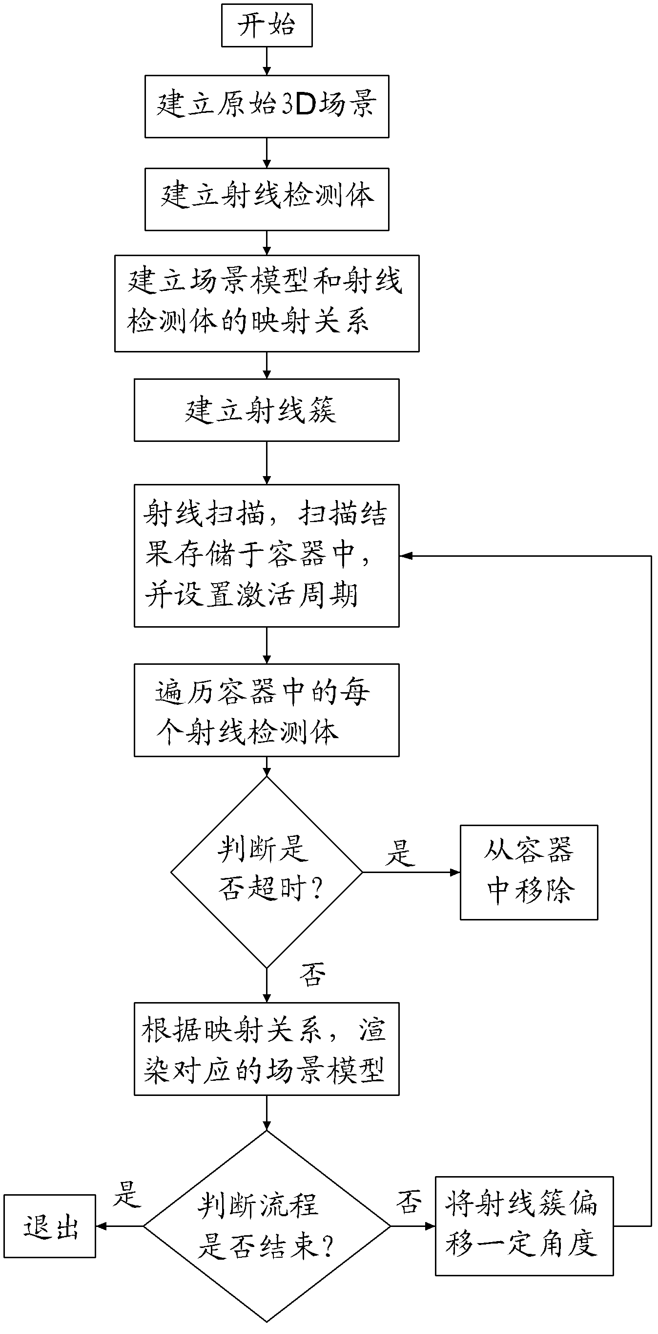
[0025] see Figure 1 to Figure 5 As shown, the present invention provides a 3D scene clipping method based on scanning rays, comprising the steps of:

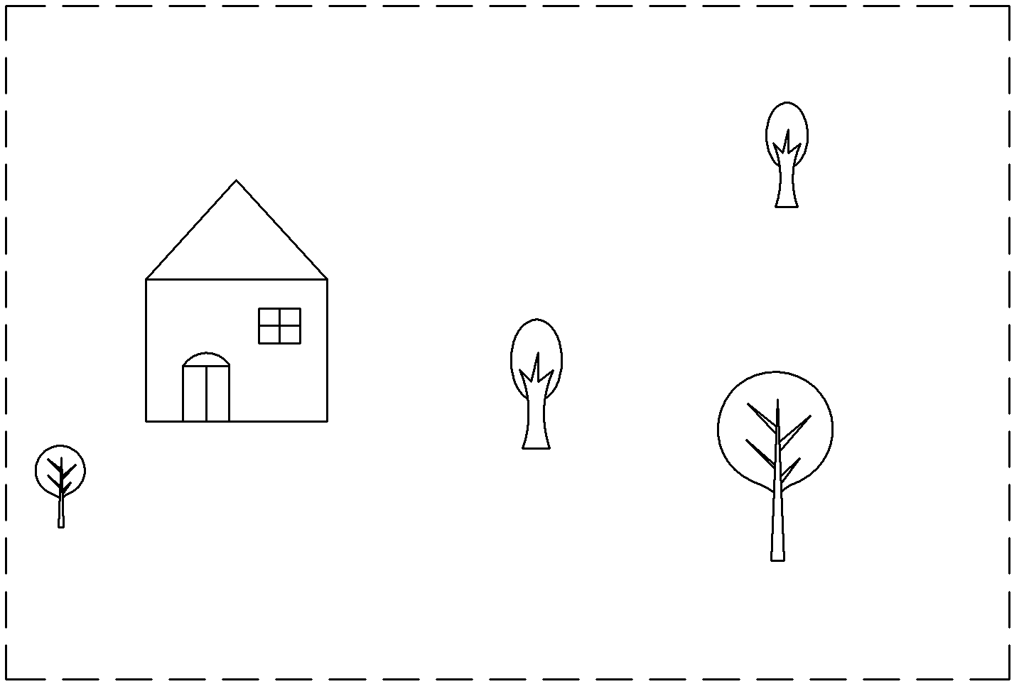
[0026] Step 10, establish the original 3D scene, such as figure 2 As shown, the 3D scene is composed of multiple scene models.

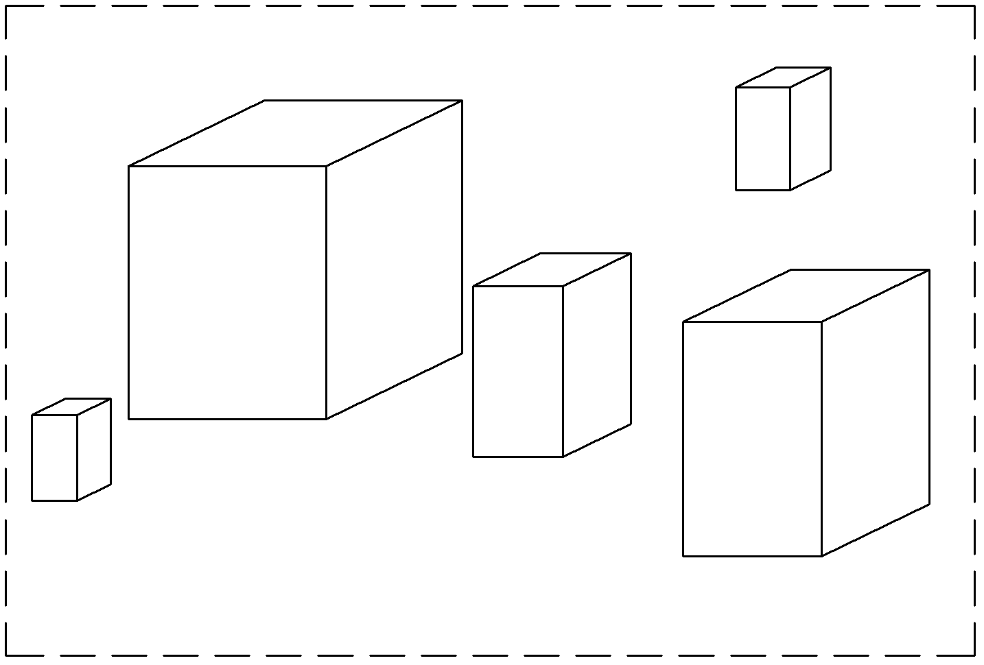
[0027] Step 20, establish a ray detection volume for each scene model, such as image 3 As shown, the ray detection body is a geometric body that wraps the scene model as much as possible, but should be as simple as possible; the complexity of the shape of the ray detection body increases with the improvement of detection accuracy and detection efficiency. In actual use, depending on the application requirements and the operating environment of the program, the shape of the geometry can be spherical, AABB bounding box, or OBB bounding box, which can be expressed by mathematical models in the program, such as spherical equations, ellipsoid equations or by A polyhedron described by multiple plane eq...


PUM


Abstract

The invention provides a 3D scene cutting method based on scanning a ray. The method is characterized by: aiming at a scene model in a 3D scene, establishing a ray detection body, wherein the ray detection body wraps the scene model as much as possible; establishing a mapping relation of each ray detection body and the corresponding scene model; according to a current coordinate and a current orientation of a scene camera, establishing a ray cluster uniformly distributed in a scene camera cone, wherein the length of the each ray in the ray cluster is not less than the length of a far cutting surface of the camera; in a current frame, traversing the each ray in the ray cluster according to a certain sequence, carrying out an intersection detection on the ray detection body, if one ray detection body is hit by the ray, storing the ray detection body in a container, traversing the each ray detection body in the container, finding the scene model corresponding to the ray detection body according to the mapping relation and rendering the scene model. According to the invention, during an operating period, the ray detection body substitutes a scene model so as to carry out rapid ray scanning. The method is suitable for various kinds of 3D scene management.

Description

【Technical field】 [0001] The invention relates to a clipping method for real-time rendering of a 3D scene, which mainly solves the problem of judging the visibility of a 3D scene model by performing fast ray scanning detection on the model in the scene. 【Background technique】 [0002] A 3D scene is composed of a certain number of scene models. How to well represent a complex scene containing thousands of objects, so scene management is required to provide a good hierarchical relationship for the scene for better screening (Culling) and Hidden surface removal. Scene management involves visibility processing and collision detection. The system needs to determine which parts of the scene are within the visibility constraints. At present, mature technical solutions for 3D scene organization and management mainly include BSP (Binary Space Partitioning trees), Portal, quadtree, octree, etc. These technologies require spatial segmentation of the scene during scene production, and...

Claims


Application Information

Patent Timeline
Patent Type & Authority Patents(China)
IPC IPC(8): G06T15/30
Inventor 罗丁
Owner FUJIAN TIANQU NETWORK TECH
Learn More