Temperature and electricity double-controlled fire extinguishing apparatus
A technology of fire extinguishing device and thermoelectricity, which is applied in fire rescue and other directions, can solve single problems, achieve good application prospects and economic benefits, increase the effectiveness of use, and reduce losses
- Summary
- Abstract
- Description
- Claims
- Application Information
AI Technical Summary
Problems solved by technology
Method used
Image
Examples
Embodiment 1
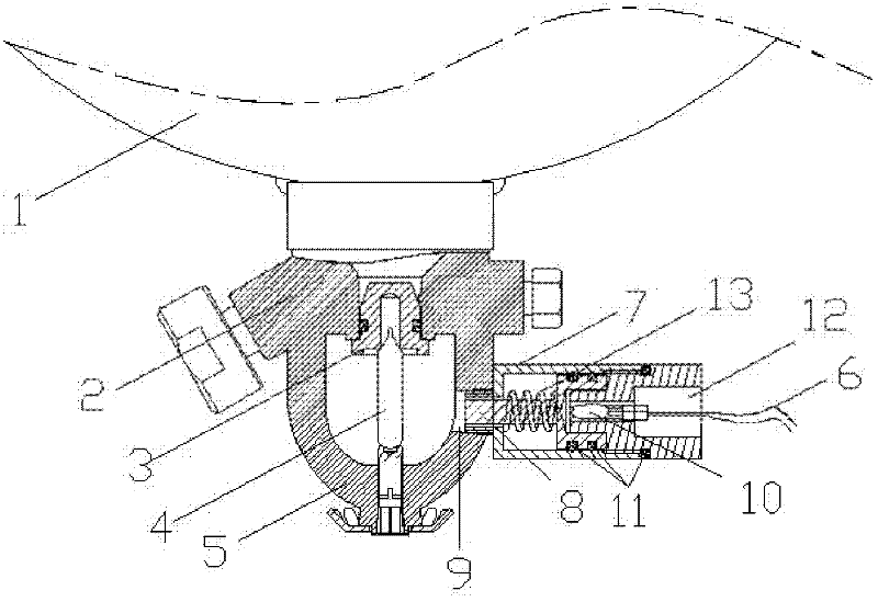
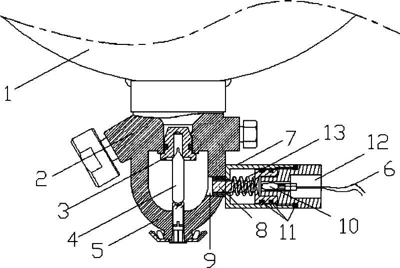
[0025] Such as figure 1 The shown thermoelectric dual control fire extinguishing device includes a stored pressure fire extinguisher 1, the stored pressure fire extinguisher 1 is provided with a nozzle 2, and the nozzle 2 is provided with a sealing valve 3, a constant temperature glass column 4, and a glass column fixing seat 5. The sealing valve 3 seals the outlet of the nozzle 2, and the two ends of the constant temperature glass column 4 respectively resist the sealing valve 3 and the glass column fixing seat 5, so that the sealing valve 3 and the cylinder of the stored pressure fire extinguisher 1 form an airtight container, and the fire extinguishing agent and the driving gas Preloaded in fire extinguisher container. The temperature and electricity dual control fire extinguishing device of the present invention is also provided with an electric control striker 7, the electric control striker 7 is aligned with the constant temperature glass column 4, installed on the glas...
Embodiment 2
[0037] In this embodiment, the driving device is an electromagnet driving device, which includes a coil, a power cord connected to the coil, a hollow iron core with transparent ends, and a pushing part. Inside the control impactor 7, the coil is wound on the outside of the iron core; the driving part is a permanent magnet rod, and the permanent magnet rod is slipped in the inner cavity of the iron core, and one end of the permanent magnet rod is against the root of the firing pin 8 .
[0038] The working principle is: add a certain voltage at both ends of the coil, so that a certain current flows through the coil, thereby generating an electromagnetic effect, and a magnetic field is generated around the iron core, and the N and S poles of the magnetic field are just in line with the N and S poles of the permanent magnet rod. On the contrary, according to the principle that the magnetic poles of the same name repel each other, the magnetic field of the permanent magnet bar and ...
Embodiment 3
[0040] In this embodiment, the driving device is a motor device. According to the difference of the power transmission mode between the motor device and the striker 8, the relative positions of the motor device and the striker 8 are also different. If the motor device is in a reciprocating motion, the motor device can be in direct contact with the striker 8 and installed behind the striker 8 . The push rod of the motor device pushes out the firing pin 8, the firing pin 8 breaks the constant temperature glass column 4, the push rod of the motor device returns, and the return spring 13 pushes the firing pin 8 back simultaneously, and the electronically controlled striker 7 returns to its original state.
[0041] If the motor device is in the form of rotation, the motor device can be installed on the side or rear of the striker 8. After gear transmission, when the motor rotates in the forward direction, the striker 8 is pushed out. After a certain distance, the motor rotates in t...
PUM
 Abstract
Description
Claims
Application Information
 - R&D
- Intellectual Property
- Life Sciences
- Materials
- Tech Scout
- Unparalleled Data Quality
- Higher Quality Content
- 60% Fewer Hallucinations
Browse by: Latest US Patents, China's latest patents, Technical Efficacy Thesaurus, Application Domain, Technology Topic, Popular Technical Reports.
© 2025 PatSnap. All rights reserved.Legal|Privacy policy|Modern Slavery Act Transparency Statement|Sitemap|About US| Contact US: help@patsnap.com


