Incinerator

An incinerator and combustion chamber technology, applied in the field of incinerators, can solve problems such as the inability to increase the combustion temperature, block the discharge port of the cyclone separator, block the hole path, etc., so as to ensure high constant temperature incineration requirements and avoid secondary pollution problems. , The effect of stable and reliable work

Active Publication Date: 2015-06-10
江苏道明化学有限公司
View PDF6 Cites 0 Cited by
  • Summary
  • Abstract
  • Description
  • Claims
  • Application Information

AI Technical Summary

Problems solved by technology

When the above-mentioned structure was used by the applicant for a long time, it was found that although the water and steam heating components can be arranged independently from the combustion chamber, thereby ensuring that the temperature in the combustion chamber is always at a high constant temperature state, however, its own structure and functions are still slightly inconspicuous. Disadvantages: On the one hand, the structure and function of the cyclone separator used in the above structure is basically the same as that of the existing cyclone separator, which means that the combustion residue in the main combustion chamber can be circulated to supply the combustion function while ensuring that the hot gas can enter accurately. In the main flue, however, when there are combustibles such as plastics in the main combustion chamber, once the combustion is insufficient and there are combustion residues, the residues fall through the cyclone separator again, often forming a snowball effect in the process again, resulting in the accumulation of residues and the formation of Hard agglomerates, the hard agglomerates are not only extremely difficult to incinerate, but also have the possibility of blocking the outlet of the cyclone separator after long-term accumulation, which has just formed a vicious circle, that is, because the existing incinerator cannot Complete combustion, so it is necessary to set up a cyclone separator to realize the secondary cycle combustion of the residue that cannot be fully burned, and it is precisely because of the setting of the cyclone separator that the problem of pore blockage that often occurs inside it is caused; on the other hand , the equipment occupies a large area, and the complicated design of its cyclone separator and flue often leads to its bulky volume, which brings great trouble to the staff; in addition, the hot gas supply in the main combustion chamber is all through the main flue However, the temperature in the middle temperature zone of the main flue is too mild, which is also the main reason why the combustion temperature in the main combustion chamber has not been able to increase

Method used


Image

  • Incinerator
  • Incinerator
  • Incinerator

Examples


Embodiment Construction

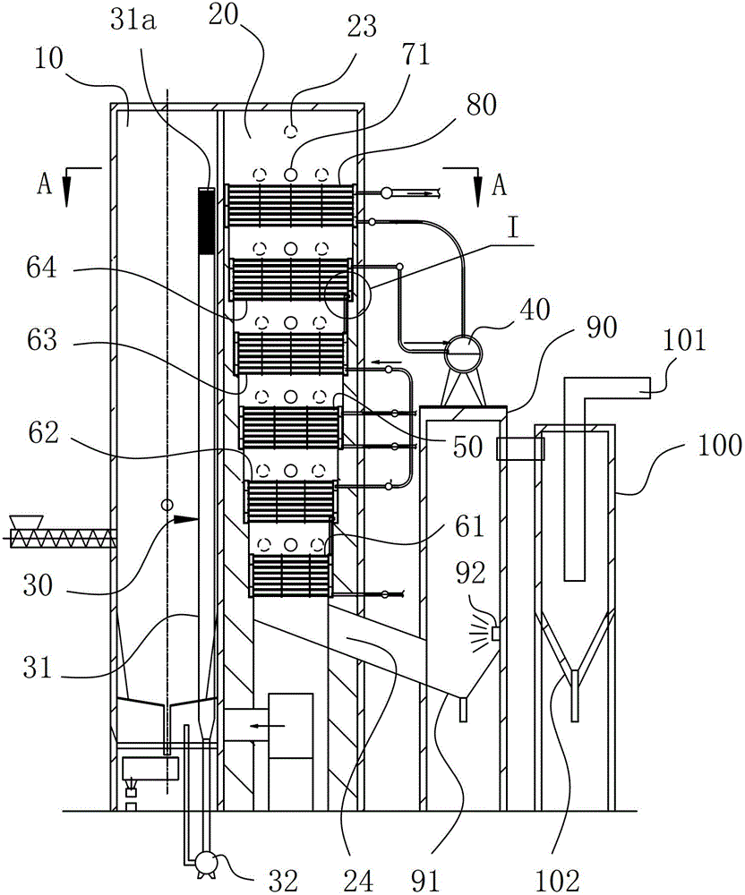
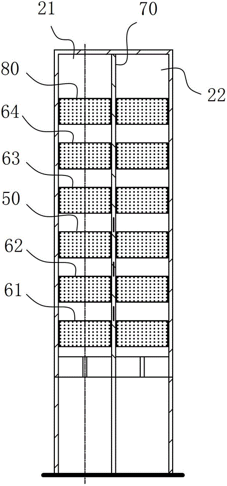
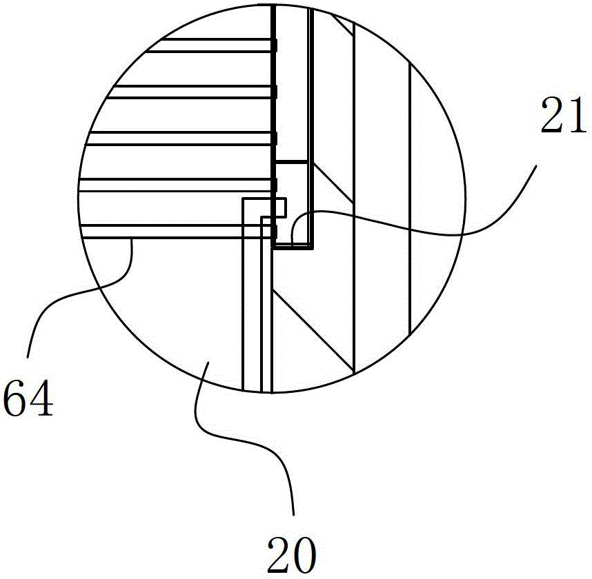
[0012] An incinerator, comprising a combustion chamber 10 and a main flue 20 for extracting heat energy in the combustion chamber 10, the incinerator also includes an air induction unit 30, and the air induction unit 30 includes an air induction pipe 31 and an air induction pipe 31 for The blower fan 32 that provides the air exhaust pipe 31 exhaust power, the air inlet end of the air induction pipe 31 is located at the upper middle position of the combustion chamber 10, and the air outlet end is arranged along and connected to the air inlet chamber at the bottom of the combustion chamber 10.

[0013] Its specific structure is as Figure 1-4 As shown, the present invention reduces its overall footprint to a certain extent by abandoning the traditional cyclone separator design, ensures its compact size, and also ensures the structural reliability of its entire body. In addition, relying on the arrangement of the air induction unit 30, by extracting part of the high-temperature h...


PUM


Abstract

The invention belongs to the field of waste incineration, and in particular relates to an incinerator. The incinerator comprises a combustion chamber, a flue collector and an air induction unit, wherein the flue collector is used for inducing heat energy in the combustion chamber out; the air induction unit comprises an air induction pipe and a fan for providing air exhaust power for the air induction pipe; and the air inlet end of the air induction pipe is positioned in the middle upper position of the combustion chamber, and the air outlet end of the air induction pipe extends and is communicated with an air inlet chamber at the bottom of the combustion chamber. By virtue of the air induction unit, when the incinerator operates, part of high-temperature gas at the heat energy outlet of the combustion chamber is extracted and discharged into the air inlet of the combustion chamber, and because the extracted heat energy is only a small part of the heat energy discharged by the combustion chamber, the high calorific value requirement on the following processes of the incinerator can be still met; the extracted heat energy can be returned to the combustion chamber again, so that the basic incineration temperature of the combustion chamber is also increased in another way, and finally, the requirements on the high-constant-temperature incineration in the combustion chamber are effectively met; and the incinerator operates stably and reliably, and has high combustion efficiency.

Description

technical field [0001] The invention belongs to the field of garbage incineration, and in particular relates to an incinerator. Background technique [0002] Garbage incineration is a municipal waste treatment method widely used in countries all over the world. Large-scale waste incineration treatment systems equipped with heat recovery and utilization devices are gradually becoming the mainstream of incineration treatment because they meet the requirements of energy recovery. Grate furnaces and circulating fluidized bed boilers are typical examples of waste incineration utilization. Their main principle is to rely on the heat generated by waste incineration to bake water-cooled wall pipes or heaters located in the main combustion chamber, left and right cyclone separators, and flues. The water-cooled wall pipe conducts heat energy into the internal storage water, and the water is heated to generate hot steam to rise, and then the hot steam enters the heater for secondary he...

Claims


Application Information

Patent Timeline
Patent Type & Authority Patents(China)
IPC IPC(8): F23G5/00F23G5/44
Inventor 李登平
Owner 江苏道明化学有限公司
Why Eureka
Try Eureka