Incinerator with fixed fire grate

A technology for fixing grate and incinerator, applied in incinerators, combustion methods, combustion types, etc., can solve the problems of aggravating the cost, difficulty and unbalance of straw incineration, and ensure efficient heat extraction and utilization effect and operation reliability. The effect of high and high incineration efficiency

Inactive Publication Date: 2014-08-20
合肥康帕因设备技术有限公司
View PDF5 Cites 3 Cited by
  • Summary
  • Abstract
  • Description
  • Claims
  • Application Information

AI Technical Summary

Problems solved by technology

At present, the above-mentioned incineration methods of straw, due to the consideration of its own rapid combustion and short combustion cycle, therefore use the rolling grate as the combustion base for continuous feed incineration, that is, rely on the conveyor belt Combustion plane, the material is input from the input end of the combustion plane, and completes the combustion and heating work during the process of running along the combustion plane, and then outputs from its output end, and its heat is introduced into the corresponding heat energy utilization component for heat energy utilization; the above scheme is currently It is being widely used in the straw incineration system. However, compared with the simplicity of the scheme, its defects cannot be underestimated: First, the straw texture is fluffy. In order to ensure its unit combustion efficiency, many incineration plants use straw Before the grass is incinerated, another processing program is set up to process it, or it is crushed in advance and compressed into a pine cone shape for incineration, or it is directly bundled and then cut section by section to be sent to the incinerator, which invisibly aggravates the The cost of straw incineration is reduced; secondly, biomass fuels such as straw, considering a series of factors such as its huge floor area, open stacking site, and simple transportation conditions, in fact its own combustion calorific value is Extremely low and unbalanced, that is to say, it may be due to the difference in material density between forage and wood, or there may be a part of the same batch of straw that is put into the furnace that burns out and the other part is difficult to burn due to excessive moisture, And because the straw is closer to each other under the action of water tension after absorbing water, it is often difficult for air to enter the inside of the straw to achieve rapid combustion, which leads to the low and non-uniformity of the actual incineration efficiency; finally, the rolling type The design of the grate structure is extremely unreasonable. Not only is its conveying length limited due to its excessive mass, which makes it impossible to realize the plan of "guaranteeing the burnout effect by long-distance displacement of materials". The moving rollers are often deformed and damaged when pulling the huge mass of the grate, which puts forward severe requirements for the practical application of the movable grate furnace
How to specifically develop a fixed grate incinerator with a simpler structure and more convenient use, so as to ensure the extraction of combustion heat energy and effectively ensure the high efficiency of material incineration, overcoming traditional biomass materials The unevenness of the calorific value, avoiding the phenomenon of excessive waste residue and difficult post-processing due to low combustion efficiency, is a technical problem to be solved urgently by those skilled in the art in the past ten years

Method used


Image

  • Incinerator with fixed fire grate
  • Incinerator with fixed fire grate
  • Incinerator with fixed fire grate

Examples


Embodiment Construction

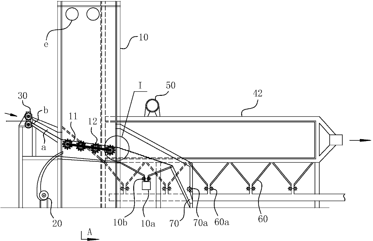
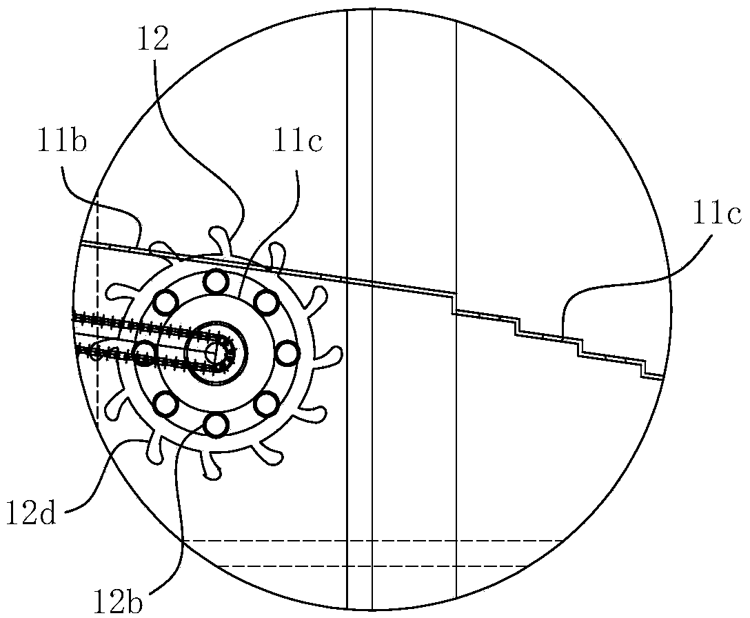
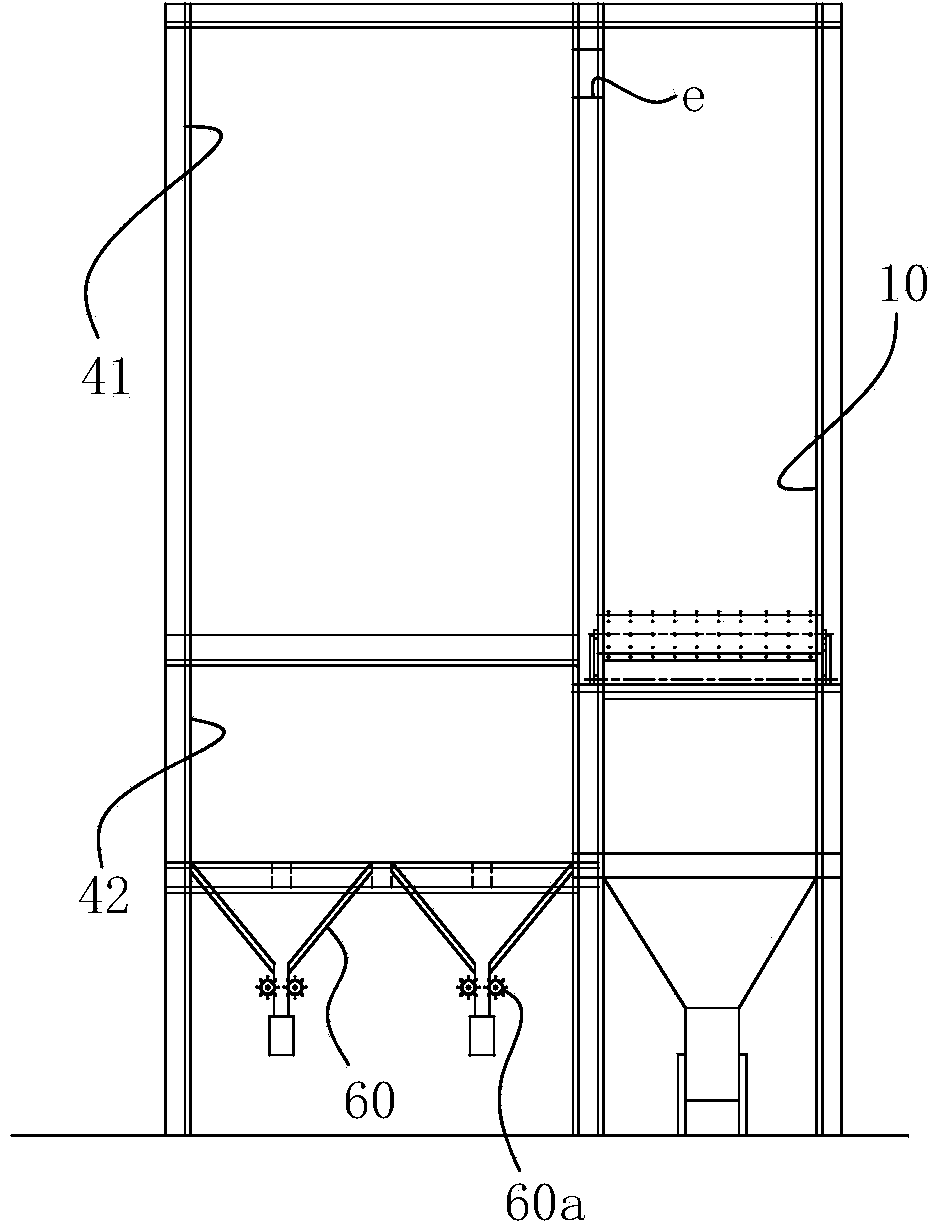
[0041] For ease of understanding, combined here Figure 1-8 Specifically set forth the component structure of the present invention and its specific work flow:

[0042] Concrete structure of the present invention, refer to Figure 1-8 As shown, it includes at least a fixed plate structure fire grate (that is, a loading plate 11) that is equipped with a stirring portion that has a conveying capacity; Compression molding function: the ash accumulation unit 70 is arranged at the discharge end of the bearing plate 11, so as to ensure the ability to collect and remove the burned ash. Such as Figure 1-2 and Figure 4 and Figure 6 As shown, the entire bearing plate 11 presents a knuckle and inclined surface structure with a high feed end and a low discharge end. The load plate 11 is divided into a moisture removal section 11a, a combustion section 11b, a burnout section 11c and ash slag by its working sections. The cooling section 11d, wherein the moisture discharge section 11...


PUM


Abstract

The invention belongs to the field of waste incineration devices and particularly relates to an incinerator with a fixed fire grate. The incinerator with the fixed fire grate is used for incinerating biomass materials such as straws and at least comprises a main combustion chamber, an air supply assembly and a smoke flue for guiding heat energy in the main combustion chamber out. The main combustion chamber is communicated with the smoke flue through a ventilation pipe, and a conveying and incinerating platform is arranged in the main combustion chamber and at least comprises a bearing plate and a stirring portion. The incinerator with the fixed fire grate further comprises a pushing portion, wherein an air return moisture removal cavity channel is arranged between the pushing portion and the main combustion chamber in a transition mode and forms a material conveying path for connecting the cavity of the main combustion chamber with the pushing portion, an air outlet is formed in the end of the air return moisture removal cavity channel and communicated with an external air draught fan, and the end of the air return moisture removal cavity channel and the pushing portion are positioned at the same end. The incinerator with the fixed fire grate is high in operation reliability and incineration efficiency, low in cost and capable of ensuring incineration at high and constant temperature and extracting and utilizing efficient heat energy of biomass fuel.

Description

technical field [0001] The invention belongs to the field of garbage incineration equipment, and in particular relates to a fixed grate incinerator for burning straw and other biomass materials. Background technique [0002] With the gradual advancement of social science and technology, the country's quality supervision of the air environment has become increasingly strict, and the past self-incineration of biomass materials such as straw has been unable to be recognized by the country. Most of the existing treatment methods for the above-mentioned materials are purchased by the incineration plant and sent to a special movable grate furnace for systematic incineration. The various gases and smoke produced by the incineration are also purified by the incineration plant itself. Conditions to be purified before being discharged into the outside air. At present, the above-mentioned incineration methods of straw, due to the consideration of its own rapid combustion and short com...

Claims


Application Information

Patent Timeline
Patent Type & Authority Applications(China)
IPC IPC(8): F23G5/00F23G5/02F23G5/44
Inventor 李登平韩莹
Owner 合肥康帕因设备技术有限公司
Why Eureka
Try Eureka