
A power heat pipe device
A technology of power heat pipes and catheter tubes, applied in the field of heat exchange, can solve the problems of insufficient circulation power and incomplete gas-liquid separation, etc., reduce the restrictions on use conditions, solve the problems of height difference and transportation distance, and improve heat exchange efficiency Effect
- Summary
- Abstract
- Description
- Claims
- Application Information
AI Technical Summary
Problems solved by technology
Method used
Image

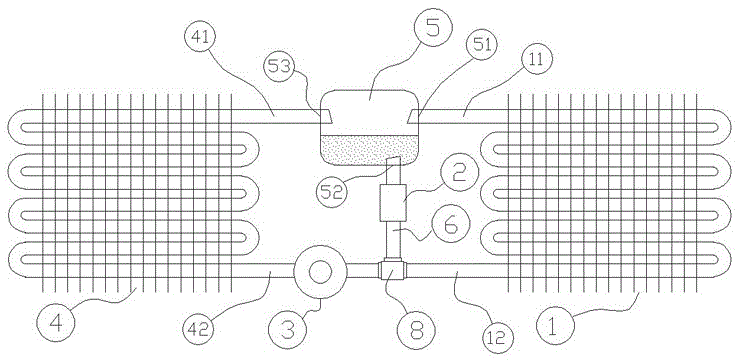
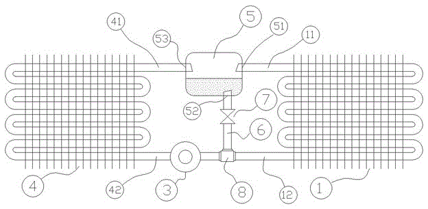
Examples
specific Embodiment approach 2
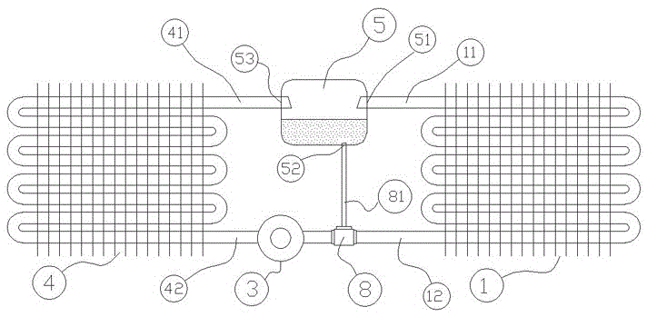
[0030] image 3 exist figure 1 On the basis of the power heat pipe device shown, the liquid return device (2) is a vertical liquid guide tube (81) with a certain size and cross-section. The vertical liquid guide tube (81) should be as straight as possible, and its length should be the The distance from the liquid tank (5) to the tee pipe (8) is matched, and its flow rate is controlled by the cross section of its liquid inlet. The highest point in the vertical direction of the entire pipeline cannot exceed the liquid level in the liquid storage tank (5). height, and require the liquid storage tank (5) to be on the upper part of the tee pipe (8), so that there is a certain height difference between the two, so that the liquid in the liquid storage tank (5) passes through the vertical catheter (81) due to gravity Return to the three-way pipe (8), and send to the evaporator (4) through the circulation pump (3). Other components are the same as in Embodiment 1.
specific Embodiment approach 3
[0031] In a specific environment, in order to exchange the functions of the condenser (1) and the evaporator (4) in the device, that is, the condenser (1) acts as an evaporator, and the evaporator (4) acts as a condenser, Improvements are made on the basis of the first embodiment.
[0032] The circulation pump (3) is replaced by a one-way circulation pump with a two-way power motor system (such as Roots motor) that can directly change the direction, and the pipeline from the connection interface (52) of the liquid storage tank (5) passes through the liquid return device ( 2) It is no longer a branch, but divided into two branches, each branch is connected to a check valve, the direction of the check valve is to flow out from the interface (52), and the check valve installed on one branch The outlet of valve one (21) is connected to the three-way pipe (32) between the circulating pump (3) and the condenser (1), and the outlet of one-way valve two (22) installed on the other bra...
specific Embodiment approach 4
[0038] Figure 5 exist figure 1 On the basis of the power heat pipe device shown, the liquid return device (2) is a liquid return hole (9), which is located at a suitable position on the condenser liquid guide (12). This device requires the condenser liquid guide The pipe of (12) passes through the liquid storage tank (5), and the pipe of the condenser liquid guide (12) is at the lower part of the liquid level in the liquid storage tank (5), and its position is as close as possible to the bottom of the liquid storage tank (5). As a result, the liquid refrigerant stored in the liquid storage tank (5) is concentrated in the condenser liquid pipe (12) through the liquid return hole (9) and the refrigerant output from the liquid outlet of the condenser (1) due to the action of gravity and pressure. It is sent to the evaporator (4) by the circulation pump (3) for circulation. Other components are the same as those in Embodiment 1 or Embodiment 2.
PUM
 Abstract
Description
Claims
Application Information