Supercharge Your Innovation With Domain-Expert AI Agents!

Film riding seal for turbines

A technology for seals and turbines, which is applied in the direction of engine components, mechanical equipment, machines/engines, etc., and can solve the problems that seals have not been widely used

Inactive Publication Date: 2012-10-17
GENERAL ELECTRIC TECH GMBH
View PDF6 Cites 3 Cited by
  • Summary
  • Abstract
  • Description
  • Claims
  • Application Information

AI Technical Summary

Problems solved by technology

[0009] However, given that membrane-controlled seals require very precise machining and control of the sealing surfaces and their distances, this particular type of seal has not found widespread use in the power generation industry

Method used


Image

  • Film riding seal for turbines
  • Film riding seal for turbines
  • Film riding seal for turbines

Examples


Embodiment Construction

[0031] First, details of aspects and examples of the present invention are described in greater detail in the following description relating to the so-called "compact diaphragm" design as shown in Figure 1, which reproduces commonly-owned published U.S. Patent Application No. 2008 Relevant features of Figure 2 in / 0170939.

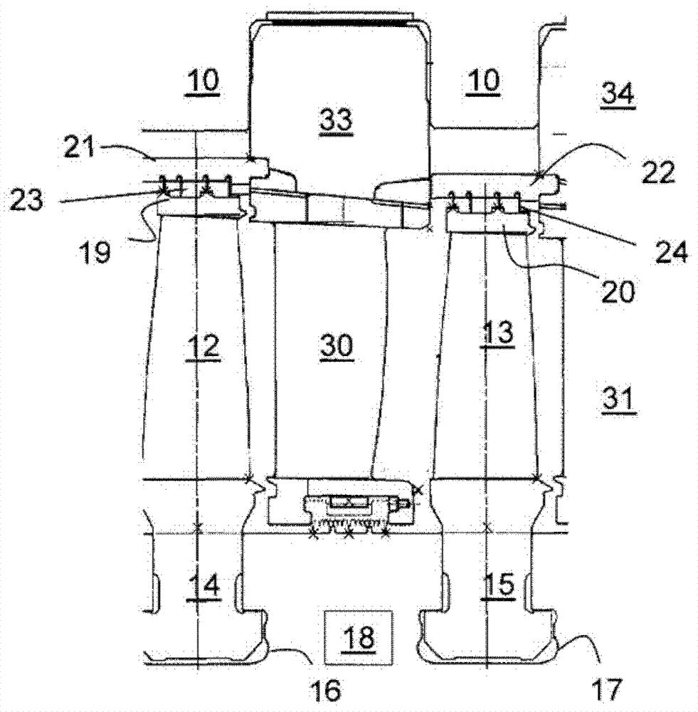
[0032] A partial radial cross-sectional sketch of an axial flow turbine is shown in Figure 1 , showing the section of a ring of stationary blades or diaphragms located between successive annular rows of moving blades 12, 13 in a steam turbine. The moving blades are each provided with a radially inner “T-root” portion 14 , 15 which sits in a corresponding slot 16 , 17 machined in the edge of the rotor drum 18 . Their ends are also provided with radially outer members called caps 19 , 20 . In the example shown, the cover carries the moving parts of the labyrinth seal. Delimited segmented rings 21, 22 support the stationary part of the seal. They are rigid...


PUM


Abstract

An seal is described for a turbine with a first sealing surface mounted on a stationary part of a turbine and a second sealing surface mounted on a rotating part of the turbine, the surfaces are structured such that in operation the thin film of a fluid medium is generated between the two surfaces reducing contact and / or leakage with at least one of the first or second sealing surface mounted such that it is subject to a retracting force which opens the seal while stationary or at slow rotation speeds of the turbine and subject to a force counteracting the retracting force at operational rotation speeds of the turbine. The surface of the sealing face may incorporate patterns straight or helical in nature to help induce the fluid into the gap and maintain the fluid film.

Description

technical field [0001] The present invention relates to a seal mounted between rotating and stationary parts of a turbomachine, in particular between the tip of a rotating turbine blade and a stationary casing or extension thereof. Background technique [0002] In the following description, the term "turbine" is used to refer to a rotary engine having a stator and a rotating part in force engagement through a fluid medium such as water or gas. Of particular interest for the present invention are axial flow turbines comprising radially fixedly mounted stator blades or buckets alternating with radially mounted moving rotor blades. Movement generally refers to movement relative to a housing or enclosure. [0003] Many components of a turbomachine experience loss of efficiency due to leakage of fluid media into components of the turbomachine outside of the required flow path. Important leakage paths lie, for example, between the rotor and the casing, or between the tips of sta...

Claims


Application Information

Patent Timeline
IPC IPC(8): F01D11/10F01D11/04
CPCF01D11/08F01D11/10F01D11/025F01D11/04F05D2240/55F01D11/14
Inventor C·W·芬内尔V·斯特凡尼策
Owner GENERAL ELECTRIC TECH GMBH
Features
  • R&D
  • Intellectual Property
  • Life Sciences
  • Materials
  • Tech Scout
  • Unparalleled Data Quality
  • Higher Quality Content
  • 60% Fewer Hallucinations
Learn More