Multicast service realizing method and equipment thereof

An implementation method and technology of multicast services, applied in the branch office to provide special service devices, data exchange details, digital transmission systems, etc., can solve the problem of occupying the capacity of forwarding entries, etc.

Active Publication Date: 2012-10-17
XINHUASAN INFORMATION TECH CO LTD
View PDF7 Cites 15 Cited by
  • Summary
  • Abstract
  • Description
  • Claims
  • Application Information

AI Technical Summary

Problems solved by technology

However, a large number of useless multicast forwarding entries will occupy the tight capacity of forwarding entries

Method used


Image

  • Multicast service realizing method and equipment thereof
  • Multicast service realizing method and equipment thereof
  • Multicast service realizing method and equipment thereof

Examples


Embodiment 1

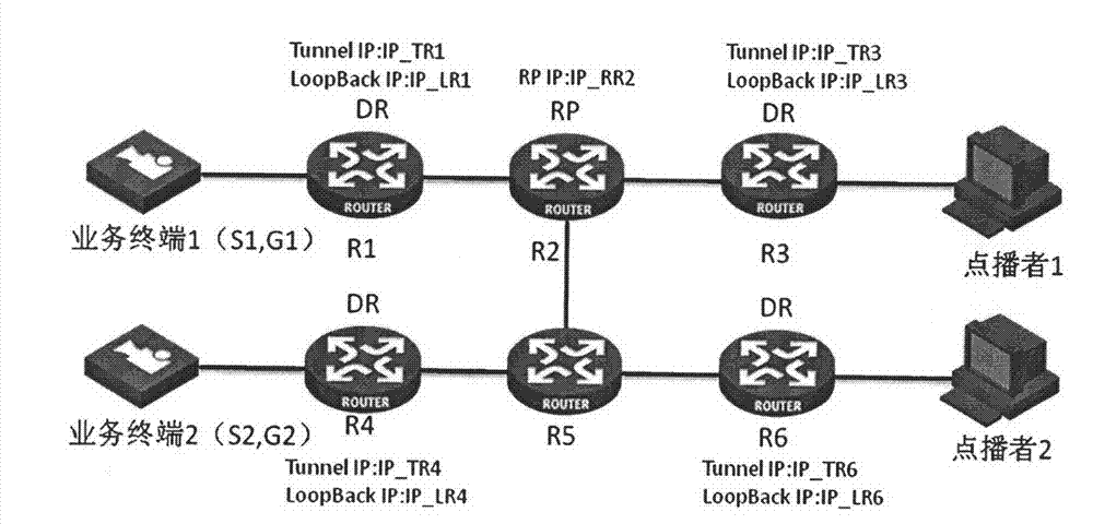
[0073] This embodiment describes the process of realizing the multicast service by establishing a multicast tunnel between the DR on the multicast receiving side and the DR on the multicast source side.

[0074] In the embodiment of the present invention, during network configuration, related tunnel configurations are performed on the DR connected to the multicast source and the DR connected to the multicast receiving device respectively. The embodiment of the present invention takes GRE (Generic Routing Encapsulation, general routing encapsulation) technology as an example to establish a tunnel. In this case, the following tunnel configuration is performed on the DR:

[0075] Create a tunnel interface on each DR, set the IP address of the tunnel interface on each DR so that all the IP addresses of the tunnel interfaces are in the same network segment, and configure the local loopback port of the device as the source address of the tunnel interface. Configure the tunnel mode a...

Embodiment 2

[0116] This embodiment describes the process of realizing the multicast service by establishing a multicast tunnel between the DR on the multicast receiving side and the DR on the multicast source side. The main difference between Embodiment 2 and Embodiment 1 is: after receiving the IGMP membership report message sent by the multicast receiving device, the DR at the multicast receiving side sends PIM(*, G) to the corresponding multicast group RP according to the existing method Join message, which does not carry the multicast GRE tunnel configuration information of the DR on the multicast receiving side and the specific service flag used to identify the round-robin service. Instead, when the DR on the multicast receiving side receives the multicast data message, it performs SPT During handover, the multicast GRE tunnel configuration information of the DR on the multicast receiving side is carried in the PIM(S, G) join message and sent.

[0117] Specifically, after receiving t...

Embodiment 3

[0123] This embodiment describes the process of establishing a multicast tunnel between the DR and the RP at the multicast receiving side to realize the multicast service.

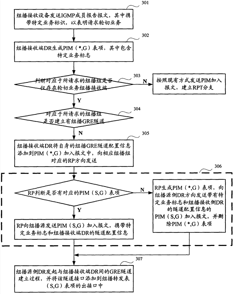
[0124] In this embodiment, after the DR at the multicast receiving side receives the IGMP membership report message carrying the specific service flag, it generates a PIM (*, G) entry with the specific service flag, and determines that it corresponds to the requested joining If the multicast group G of the multicast group G only has a multicast receiving device for the multicast service and the multicast GRE tunnel has not been established for the multicast group G requested to join, look up the RP information corresponding to the table entry, and according to the found RP information A PIM (*, G) Join message about the multicast group G is directly unicasted to the corresponding RP, which carries GRE tunnel configuration information and a specific service flag. After receiving the PIM(*, G) join message, ...


PUM


Abstract

The invention discloses a multicast service realizing method and equipment thereof. According to the multicast service realizing method provided by the invention, if a DR (Data Recorder) of an assigned router on a receiving side of a given multicast group only has a receiver of a specific multicast service, a PIM (Protocol Independent Multicast) adding message with a specific service mark and channel configuration information is sent to the upstream after the DR receives a message reported by a member of an IGMP (Internet Group Management Protocol); an intermediate router can only transmit the PIM adding message without establishing a corresponding multicast list item; after the PIM adding message is sent to a DR on a multicast source side, a channel is established through dynamic negotiation of the DR on the multicast source side and the DR on the receiving side; and an outlet interface of the channel is additionally arranged on the DR on the multicast source side. Therefore, multicast data to given multicast group receiving equipment is directly sent to the DR on the receiving side through the channel, and sent to receiving equipment after being unpackaged, so that the occupied rate of list item sources on a multicast transmission link is reduced.

Description

technical field [0001] The invention relates to multicast technology in the field of communication, in particular to a multicast service realization method and equipment thereof. Background technique [0002] IP video surveillance has become the mainstream and future of the security field. In the live video-on-demand service in the monitoring service, there is a requirement that multiple video-orderers watch a certain camera scene at the same time. Obviously, IP multicast is a good way to solve this demand. [0003] figure 1 A typical networking is shown, in which the PIM (Protocol Independent Multicast, Protocol Independent Multicast) protocol is enabled on the router. If the two monitoring hosts and the TV wall want to order the video stream of the same camera at the same time, then the camera only needs to output one multicast stream, the router Rtr-1 copies two multicast streams, and the router Rtr-3 copies two multicast streams. stream. In this way, compared with u...

Claims


Application Information

Patent Timeline
Patent Type & Authority Applications(China)
IPC IPC(8): H04L12/56H04L12/18
Inventor 林鹏程周迪
Owner XINHUASAN INFORMATION TECH CO LTD
Why Eureka
Try Eureka