Small-loop antenna for ultra-high-frequency detection of partial discharge

A partial discharge and ultra-high frequency technology, which is applied to the loop antenna with a ferromagnetic material core, and to test the dielectric strength, etc., can solve the problems of narrow antenna detection frequency band, low output impedance, narrow direction angle, etc., and achieve easy impedance Matched, high-gain, high-sensitivity effects

Active Publication Date: 2012-10-24
ELECTRIC POWER RESEARCH INSTITUTE, CHINA SOUTHERN POWER GRID CO LTD +1
View PDF8 Cites 3 Cited by
  • Summary
  • Abstract
  • Description
  • Claims
  • Application Information

AI Technical Summary

Problems solved by technology

At present, the antennas commonly used for on-line partial discharge monitoring of transformers for UHF detection mainly include Archimedes double-arm planar helical antennas, conical antennas, and dipole antennas. Practical application experience shows that the detection frequency band of ex

Method used


Image

  • Small-loop antenna for ultra-high-frequency detection of partial discharge
  • Small-loop antenna for ultra-high-frequency detection of partial discharge
  • Small-loop antenna for ultra-high-frequency detection of partial discharge

Examples


Embodiment Construction

[0027] The preferred embodiments of the present invention will be described in detail below in conjunction with the accompanying drawings; it should be understood that the preferred embodiments are only for illustrating the present invention, rather than limiting the protection scope of the present invention.

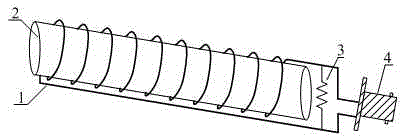
[0028] figure 1 It is a structural schematic diagram of the small loop antenna of the present invention, as shown in the figure: a small loop antenna for partial discharge ultra-high frequency detection provided by the embodiment of the present invention, including a wire layer 1, a dielectric layer 2, a cable BNC connector 4 and a matching resistor 3. The wire layer 1 is a continuous wire arranged on the surface of the dielectric layer 2, and the wire is evenly wound in a spiral shape along the cross-section of the dielectric layer. The cross section of the dielectric layer 2 is a circular surface, the head and end of the wire layer 1 are respectively connected to the ...


PUM

PropertyMeasurementUnit
Radiusaaaaaaaaaa
Diameteraaaaaaaaaa
Lengthaaaaaaaaaa

Abstract

The invention discloses a small-loop antenna for ultra-high-frequency detection of partial-discharge. The small-loop antenna comprises a dielectric layer, a conductor layer, a matching resistor and a feed terminal, wherein conductors are uniformly wound on the surface of a magnetic core; and the feed terminal is in parallel connection with the matching resistor and is used for feeding in a coaxial feeding manner. The small-loop antenna disclosed by the invention has the advantages of good directivity, wide frequency band, small standing-wave ratio and convenience in impedance matching, thus being capable of meeting the requirements on the online-monitoring ultra-high-frequency detection of the partial discharge in a power transformer.

Description

technical field [0001] The invention relates to the field of antenna design, in particular to a small-loop antenna for partial discharge ultra-high frequency detection designed using the principle of a loop antenna. Background technique [0002] The transformer is one of the most critical equipment in the power system. Its normal operation is an important guarantee for the safe, reliable, high-quality and economical operation of the power system. It is necessary to prevent and reduce the occurrence of transformer failures and accidents to the greatest extent. However, due to the long-term operation of transformers, faults and accidents cannot be completely avoided, and there are many reasons for causing faults and accidents. In transformer faults, insulation faults account for a high proportion, and partial discharges will occur before insulation faults occur. Therefore, through online monitoring of transformer partial discharges, latent faults inside the transformer can be ...

Claims


Application Information

Patent Timeline
IPC IPC(8): G01R31/12H01Q7/06
Inventor 李剑赵林杰黎小林孙夏青赵宇明吕金壮罗兵杜林王有元陈伟根廖瑞金杨丽君
Owner ELECTRIC POWER RESEARCH INSTITUTE, CHINA SOUTHERN POWER GRID CO LTD
Why Eureka
Try Eureka