NMOSFET terahertz detector based on dielectric resonant antenna and method

A technology of a dielectric resonant antenna and a terahertz detector, which is applied in the terahertz field, can solve the problems of large loss of the terahertz antenna, affecting the detection efficiency and detection sensitivity of the NMOSFET terahertz detector, and reducing the gain and radiation efficiency of the terahertz antenna. To achieve the effect of accurate detection

Active Publication Date: 2019-03-26
GUANGDONG UNIV OF TECH
View PDF7 Cites 2 Cited by
  • Summary
  • Abstract
  • Description
  • Claims
  • Application Information

AI Technical Summary

Problems solved by technology

[0002] Terahertz (Terahertz, THz) usually refers to electromagnetic waves with a frequency of 0.1-10THz (wavelength 0.03-3mm), and its long-wave band overlaps with millimeter waves (submillimeter waves). The short-wave band overlaps with the infrared, and its development mainly relies on photonics science and technology. It can be seen that the terahertz wave is the frequency band for the transition from macro-electronics to micro-photonics, so it occupies a special position in the electromagnetic spectrum. However, for a long time due to the lack of effective Terahertz radiation generation and detection methods, resulting in insufficient research and application of electromagnetic waves in the THz frequency band, so it is called the "THz gap" in the electromagnetic spectrum
[0003] In recent years, terahertz detection based on NMOSFET has been proved to be very feasible. However, due to the limitation of CMOS technology, the traditional on-chip dipole and patch terahertz antenna in the terahertz detector have a large loss, resulting in the traditional on-chip dipole The gain and radiation efficiency of terahertz antennas such as poles and patches are greatly reduced, which greatly affects the detection efficiency and detection sensitivity of NMOSFET terahertz detectors

Method used


Image

  • NMOSFET terahertz detector based on dielectric resonant antenna and method
  • NMOSFET terahertz detector based on dielectric resonant antenna and method
  • NMOSFET terahertz detector based on dielectric resonant antenna and method

Examples


Embodiment Construction

[0039] The following will clearly and completely describe the technical solutions in the embodiments of the present invention with reference to the accompanying drawings in the embodiments of the present invention. Obviously, the described embodiments are only part of the embodiments of the present invention, not all of them. Based on the embodiments of the present invention, all other embodiments obtained by persons of ordinary skill in the art without creative efforts fall within the protection scope of the present invention.

[0040]It should be noted that if there is a directional indication (such as up, down, left, right, front, back...) in the embodiment of the present invention, the directional indication is only used to explain the position in a certain posture (as shown in the accompanying drawing). If the specific posture changes, the directional indication will also change accordingly.

[0041] In addition, if there are descriptions involving "first", "second" and s...


PUM


Abstract

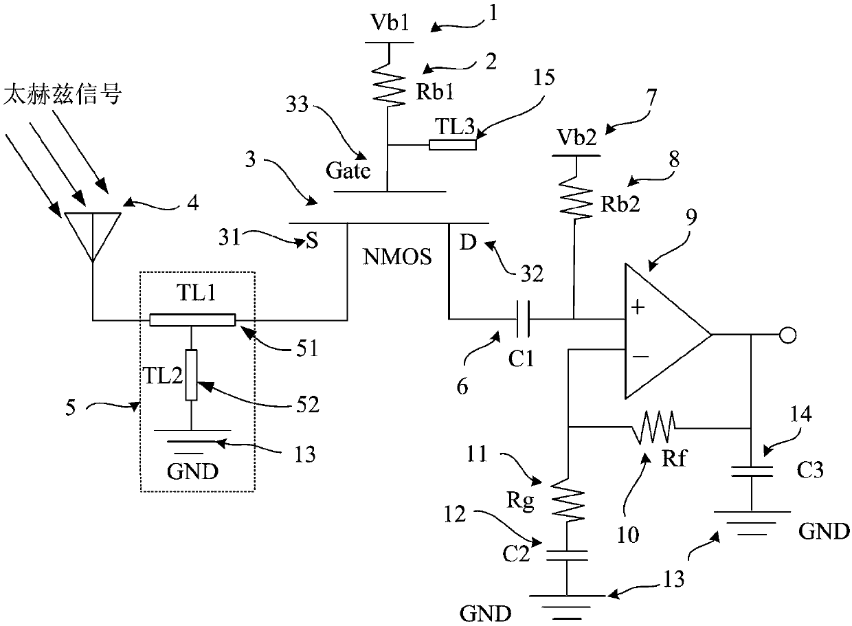
The invention discloses an NMOSFET terahertz detector based on a dielectric resonant antenna, which comprises an on-chip dielectric resonant terahertz antenna, wherein the on-chip dielectric resonantterahertz antenna is connected with a matching network, the matching network is connected with a source electrode of the NMOSFET, a grid electrode of the NMOSFET is sequentially connected with a firstbias resistance and a first bias voltage, a third transmission line is connected with the first bias resistance and the grid electrode, a drain electrode of the NMOSFET is connected with a first blocking capacitor, the other end of the first blocking capacitor is connected with a low-noise pre-amplifier, a second bias resistance and a second bias voltage are further connected between the first blocking capacitor and the low-noise pre-amplifier in parallel, and the low-noise pre-amplifier is further provided with a voltage feedback circuit. The invention further discloses a design method of the on-chip dielectric resonant terahertz antenna. Compared with the prior art, the technical scheme of the invention effectively reduces the loss of the on-chip terahertz antenna and improves the gainand radiation efficiency of the on-chip terahertz antenna.

Description

technical field [0001] The invention relates to the field of terahertz technology, in particular to an NMOSFET terahertz detector and method based on a dielectric resonant antenna. Background technique [0002] Terahertz (Terahertz, THz) usually refers to electromagnetic waves with a frequency of 0.1-10THz (wavelength 0.03-3mm), and its long-wave band overlaps with millimeter waves (submillimeter waves). The short-wave band overlaps with the infrared, and its development mainly relies on photonics science and technology. It can be seen that the terahertz wave is the frequency band for the transition from macro-electronics to micro-photonics, so it occupies a special position in the electromagnetic spectrum. However, for a long time due to the lack of effective Terahertz radiation generation and detection methods have led to insufficient research and application of electromagnetic waves in the terahertz frequency band, which is called the "terahertz gap (THz gap)" in the elec...

Claims


Application Information

Patent Timeline
Patent Type & Authority Applications(China)
IPC IPC(8): G01V8/10H01Q1/36H01Q1/22
CPCG01V8/10H01Q1/2283H01Q1/36G06F30/36G06F30/398H01L23/66H01L2223/6655H01L2223/6677H01Q9/0485H03F3/195H03F3/45475H03F3/601H03F2200/129H03F2200/294H03F2200/451H03F2203/45116H03F2203/45526H03F2203/45528G06F30/20G06F30/39H01L2223/6627H01P1/24H01Q13/18
Inventor 马建国周绍华
Owner GUANGDONG UNIV OF TECH
Why Eureka
Try Eureka