Method for calculating anisotropy azimuth angle by using dipole transverse wave logging information based on frequency domain

An anisotropy and logging data technology, applied in the field of acoustic logging data processing, can solve problems such as azimuth dispersion and large errors

Active Publication Date: 2012-12-19
CHINA PETROLEUM & CHEM CORP +2
View PDF2 Cites 12 Cited by
  • Summary
  • Abstract
  • Description
  • Claims
  • Application Information

AI Technical Summary

Problems solved by technology

If they are not consistent, the azimuth angles calculated based on the traditional time domain are scattered and have large errors

Method used


Image

  • Method for calculating anisotropy azimuth angle by using dipole transverse wave logging information based on frequency domain
  • Method for calculating anisotropy azimuth angle by using dipole transverse wave logging information based on frequency domain
  • Method for calculating anisotropy azimuth angle by using dipole transverse wave logging information based on frequency domain

Examples


Embodiment Construction

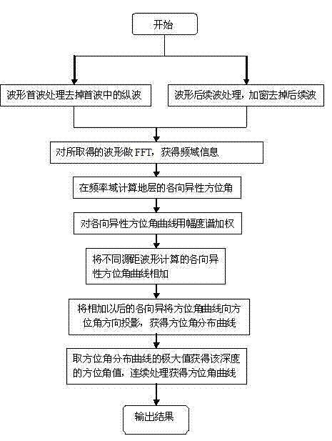
[0021] combined with figure 1 , after a long period of research and analysis and processing of the measured waveforms of various formations, and on the basis of fully grasping and analyzing a large number of processing result data, this set of specific implementation methods is proposed.

[0022] First, use the time window to select the waveform that mainly reflects the shear wave part in the measured waveform. Normally, the shear wave component occupies the main part of the measured waveform. However, for some formations, the existing dipole sound source can excite the longitudinal wave component with relatively large amplitude and frequency higher than 6kHz. Therefore, it is necessary to identify these longitudinal wave components in the original waveform before processing.

[0023] Second, select a section of shear wave waveform from the measured waveform. The specific selection method: determine a fixed time difference according to the shear wave time difference of the ...


PUM


Abstract

The invention discloses a method for calculating an anisotropy azimuth angle by using dipole transverse wave logging information based on a frequency domain. The method comprises the following steps of selecting a waveform of a transverse wave part in a dipole transverse wave logging waveform by using a time window; carrying out FFT (Fast Fourier Transform) for the selected waveform, and obtaining an anisotropy azimuth angle curve which changes with the frequency; obtaining an anisotropy azimuth angle curve after the amplitude weighting by multiplying the anisotropy azimuth angle curve by a magnitude spectrum of a waveform XX or YY; stacking the anisotropy azimuth angle curves calculated by different spacing waveforms, and obtaining a total anisotropy azimuth angle curve; fixing the interval of an azimuth angle, changing the azimuth angle, and calculating the count of azimuth angle curves in the interval of the azimuth angle; and taking a maximum value of an azimuth angle distribution curve as a value of the anisotropy azimuth angle obtained in the depth. According to the method for calculating the anisotropy azimuth angle by using the dipole transverse wave logging information based on the frequency domain, disclosed by the invention, compared with the azimuth angle calculated by a time domain, the azimuth angle is relatively concentrated, and the influence due to the waveform amplitude difference excited by dipoles in an X direction and a Y direction is small.

Description

technical field [0001] The invention belongs to the field of acoustic logging data processing methods. The invention relates to a method for calculating anisotropic azimuth angles using dipole shear wave logging data. On the basis of experiments, the influence of dipole excitation waveform amplitude inconsistency in the X and Y directions on the calculation of anisotropic azimuth angles in the time domain is studied, thus proposing Based on the method of calculating the anisotropic azimuth in the frequency domain, the calculated anisotropic azimuth is concentrated near the real value. Compared with the azimuth calculated in the time domain, its distribution is concentrated, which is affected by the amplitude of the dipole excitation waveform in the X direction and the Y direction. The difference has less impact. Background technique [0002] Traditional sonic velocity logging only utilizes the velocity information of compressional waves, and does not record subsequent waves...

Claims


Application Information

Patent Timeline
Patent Type & Authority Applications(China)
IPC IPC(8): G01V1/40E21B49/00
Inventor 朱留方吴海燕翟勇张晋言沈建国沈洪楚孙清溪阎招金王志美田艳高娜
Owner CHINA PETROLEUM & CHEM CORP
Why Eureka
Try Eureka