A self-locking slider

A technology of self-locking and locking claws, applied in the direction of sliding fastener components, applications, fasteners, etc., can solve the problem of low elasticity of the shrapnel stuck in the line, improve the appearance, reduce the stuck trouser line, and improve the elasticity and the effect of lock strength

Active Publication Date: 2016-04-27
FUJIAN SBS ZIPPER SCI & TECH CO LTD
View PDF7 Cites 0 Cited by
  • Summary
  • Abstract
  • Description
  • Claims
  • Application Information

AI Technical Summary

Problems solved by technology

[0007] The purpose of the present invention is to provide a self-locking slider to solve the problems of the self-locking slider in the prior art, such as stuck lines, hand scraping and low elastic force of the shrapnel

Method used


Image

  • A self-locking slider
  • A self-locking slider
  • A self-locking slider

Examples


Embodiment Construction

[0034] In order to further explain the technical solution of the present invention, the present invention will be described in detail below through specific examples.

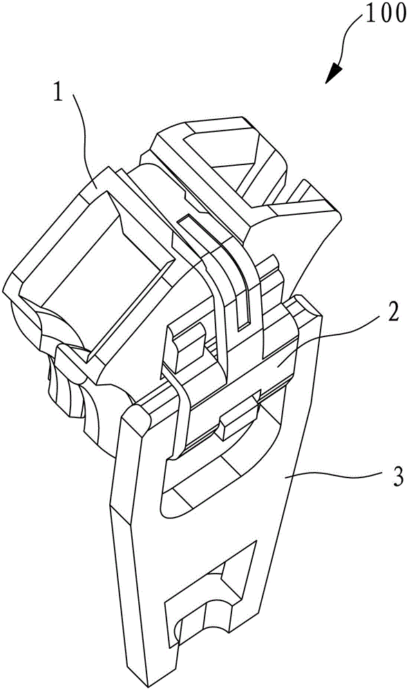
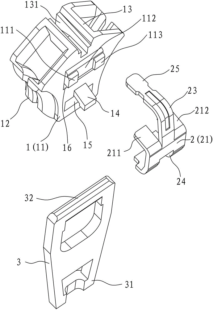
[0035] Such as Figure 1 to Figure 3 As shown, the present invention relates to a self-locking slider, which includes a slider body, an elastic piece and a pull piece, wherein:

[0036] The slider body has an upper fin, a lower fin and a guide post connecting the upper fin and the lower fin, the upper fin is formed with engaging lugs and perforations, and the perforation penetrates the two surfaces of the upper fin. A sunken groove is also formed on the upper fin.

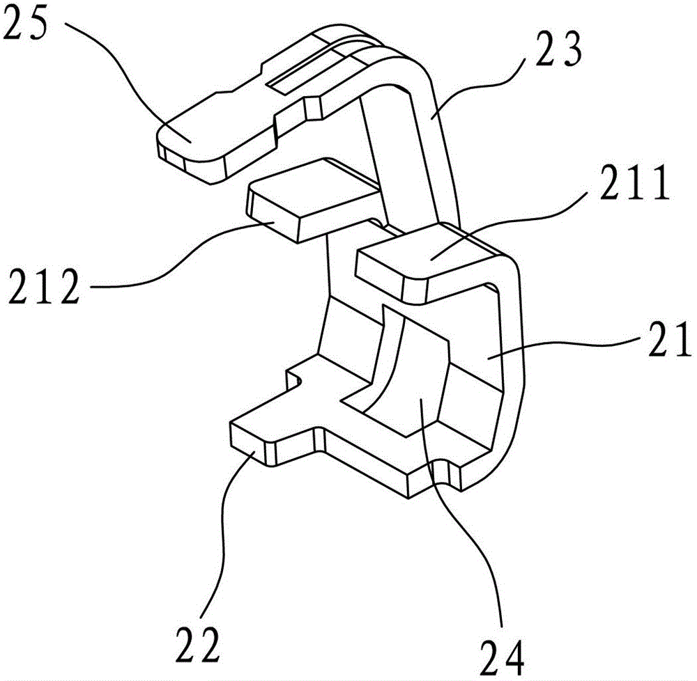
[0037] The shrapnel has a central base, a locking claw and a front end, the locking claw is located at the rear end of the central base, the front end is located at the front end of the central base, there is an opening between the central base and the locking claw, and the locking claw passes through the upper The perforation of the flap can lock...


PUM


Abstract

The invention discloses a self-locking type puller which comprises a puller body, a spring plate and a pull plate. The puller body is provided with an upper wing plate, a lower wing plate and a guide column; a meshing convex lug and a through hole are formed on the upper wing plate; the spring plate is provided with a central base, a locking claw and a front end; an opening is reserved between the central base and the locking claw; the locking claw penetrates through the through hole on the upper wing plate; the edge of the opening is meshed with the meshing convex lug; the pull plate is provided with a handle and an eccentric shaft; the eccentric shaft can be positioned in the space between the central base and the upper wing plate; the spring plate further comprises a first elastic claw and a second elastic claw which are formed at the front end of the central base; a sunk groove is formed on the upper wing plate; the front end is positioned between the first elastic claw and the second elastic claw; and both the first elastic claw and the second elastic claw are embedded in the sunk groove and are abutted to the groove wall of the sunk groove. Compared with the prior art, the self-locking type puller cannot scratch hands of a user, and the elasticity and the locking strength of the puller are greatly improved.

Description

technical field [0001] The invention relates to the field of sliders, in particular to a self-locking slider with good elasticity and locking strength. Background technique [0002] Japanese Utility Model Announcement No. 54-43841 discloses a self-locking zipper slider, which is a conventional slider on the market at present. It includes a slider body, a shrapnel and a pull piece. The central base, the locking pawl located at the rear end of the central base, and a small-width front end portion bent centrally downward from the rear end of the central base and fixed on the front surface of the guide post of the slider main body. The opposite sides of the front end portion of the central base of the spring have a pair of shoulders that pivotally engage two support points on a pair of tabs protruding from the main body of the slider. The rear end has an opening whose edge is engageable with an engagement lug located on the upper wing. In this way, through the action of the ec...

Claims


Application Information

Patent Timeline
Patent Type & Authority Patents(China)
IPC IPC(8): A44B19/30
Inventor 张田
Owner FUJIAN SBS ZIPPER SCI & TECH CO LTD
Why Eureka
Try Eureka