Planar pull head

A technology of flat and horizontal grooves, applied in clothing, sliding fastener components, applications, etc., can solve the problems of stuck lines, lower scraping hands, etc., and achieve the effects of reducing the inconvenience of stuck trouser lines, good quality, and convenient assembly

Active Publication Date: 2012-11-14
FUJIAN SBS ZIPPER SCI & TECH CO LTD
View PDF6 Cites 1 Cited by
  • Summary
  • Abstract
  • Description
  • Claims
  • Application Information

AI Technical Summary

Problems solved by technology

[0007] The purpose of the present invention is to provide a flat slider to solve the problems of the self-locking slider in the prior art, such as stuck lines, hand scraping, and the reduction of the elastic force of the shrapnel due to mutual impact between products

Method used


Image

  • Planar pull head
  • Planar pull head
  • Planar pull head

Examples


Embodiment Construction

[0034] In order to further explain the technical solution of the present invention, the present invention will be described in detail below through specific examples.

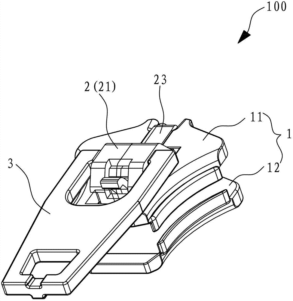
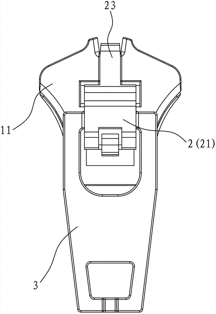
[0035] Such as Figure 1 to Figure 5 As shown, the present invention relates to a flat slider 100, which includes a slider body 1, an elastic piece 2 and a pull piece 3, wherein:

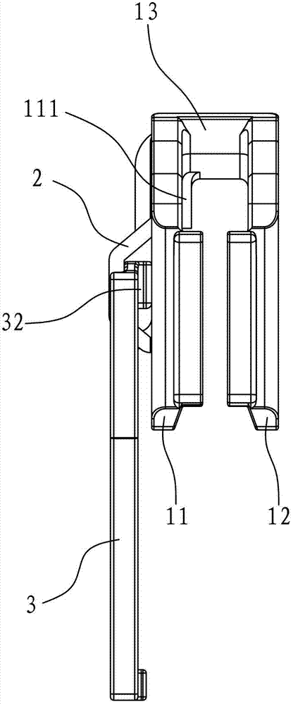
[0036] The slider body 1 has an upper wing 11, a lower wing 12 and a guide post 13 connecting the upper wing 11 and the lower wing 12, the upper wing 11 is formed with an engaging lug 14 and a perforation 15, the perforation 15 Through the two surfaces of the upper fin 11 , a T-shaped sinker 16 is formed on the upper fin 11 , including a horizontal groove 161 and a vertical groove 162 .

[0037] The elastic piece 2 has a central base 21, a locking claw 22 and a front end portion 23. There is an opening 24, the locking pawl 22 passes through the perforation 15 of the upper flap 11 to lock the zipper, the edge of the opening 24 can b...


PUM


Abstract

The invention discloses a planar pull head which comprises a pull head body, an elastic piece and a pull piece; the pull head body is provided with an upper fin, a lower fin and a guide column; the elastic piece is provided with a central base part, a locking pawl which is arranged on the rear end of the central base part and a front end part which is arranged on the front end of the central base part; the pull piece is provided with a handle and an eccentric shaft, and the eccentric shaft can be arranged in a space formed by the central base part and the upper fin and is hidden by the central base part; the planar pull head is characterized in that the elastic piece also comprises a supporting pawl which is arranged on the front end of the central base part; a T-shaped sink is arranged on the upper fin, i.e. a horizontal groove and a vertical groove are arranged; the front end part is contained in the vertical groove of the T-shaped sink, so that the upper surface of the front end part is level with or lower than the surface of the upper fin; and the supporting pawl is inlaid into the horizontal groove and is collided with the groove wall of the horizontal groove. According to the planar pull head, the problems that wires are clamped, the hands of a user are injured, the elastic force of the elastic piece easily loses effect and the like in daily use can be solved, and the planar pull head has the advantages of simplicity in structure, convenience in processing and assembly and the like.

Description

technical field [0001] The present invention relates to the field of self-locking sliders, and more specifically relates to a flat slider, which can avoid problems such as stuck lines, scraping hands, and easy failure of elastic force of shrapnel during daily use, and has the advantages of simple structure, easy processing Easy to assemble and so on. Background technique [0002] Japanese Utility Model Announcement No. 54-43841 discloses a self-locking zipper slider, which is a conventional slider on the market at present. It includes a slider body, a shrapnel and a pull piece. The central base, the locking pawl located at the rear end of the central base, and a small-width front end portion bent centrally downward from the rear end of the central base and fixed on the front surface of the guide post of the slider main body. The opposite sides of the front end portion of the central base of the spring have a pair of shoulders that pivotally engage two support points on a pa...

Claims


Application Information

Patent Timeline
Patent Type & Authority Applications(China)
IPC IPC(8): A44B19/26
Inventor 张田陈佰兴李鹏辉
Owner FUJIAN SBS ZIPPER SCI & TECH CO LTD
Why Eureka
Try Eureka