
Self-locking slider

A self-locking and locking groove technology, applied in the field of zippers, can solve problems such as bad, stuck lines, and positioning of scraping handles, etc., to reduce the inconvenience of stuck trouser lines, increase elasticity and locking strength, and improve elasticity and locking The effect of intensity

Pending Publication Date: 2018-11-02
广东海华拉链有限公司
View PDF1 Cites 0 Cited by
  • Summary
  • Abstract
  • Description
  • Claims
  • Application Information

AI Technical Summary

Problems solved by technology

[0007] Aiming at the deficiencies of the prior art, the present invention provides a self-locking slider to solve the problems of the existing self-locking sliders such as stuck lines, scraping hands and poor positioning of the pull tab

Method used


Image

  • Self-locking slider
  • Self-locking slider
  • Self-locking slider

Examples


Embodiment Construction

[0025] In order to make the above objects, features and advantages of the present invention more comprehensible, the present invention will be further described in detail below in conjunction with the accompanying drawings and specific embodiments.

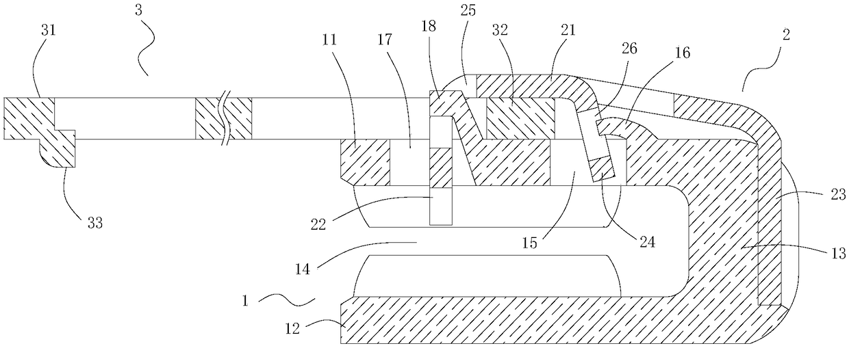
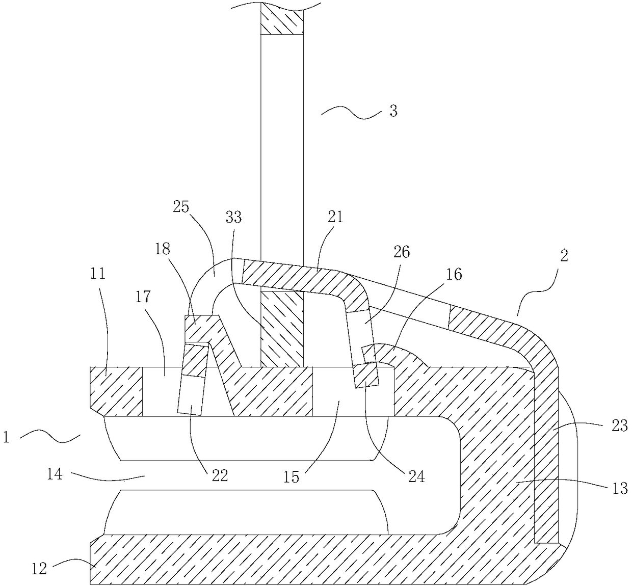
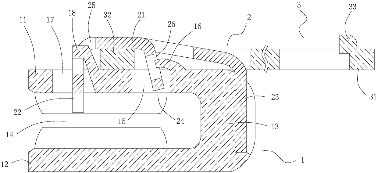
[0026] Such as Figure 1 to Figure 3 As shown, a self-locking slider includes a slider body 1, a leaf spring 2 and a pull piece 3, and these parts can be formed by stamping or machining.

[0027] The slider body 1 includes an upper wing 11 , a lower wing 12 and a guide post 13 , and the guide post 13 connects the upper wing 11 and the lower wing 12 into one body to form a chain element guide groove 14 through which the chain elements pass. An engaging hole 15 is provided at the central position of the upper wing 11 away from the front side, and a front protrusion 16 protruding from the upper surface of the upper wing 11 is formed at the front end of the engaging hole 15 . A claw hole 17 is provided at a central position away from...


PUM


Abstract

The invention discloses a self-locking slider. The slider comprises a slider body, a leaf spring and a pull tab, the slider body is provided with an upper panel, a lower panel and a guide post connecting the upper panel and the lower panel, the leaf spring is inverted and U-shaped, locking claws and hanging members with central bases are arranged at both ends of a central base, one end of the pulltab is provided with a grip portion, the other end is provided with a cam shaft, a meshing hole is formed in the front portion of the upper panel, the rear portion is provided with claw holes for thelocking claws to pass and a rear protruding piece, the front end of the central base is provided with an elastic claw extending downward and meshing with the meshing hole, an opening meshing with therear protruding piece is formed in the rear end, the cam shaft and the pull tab are disposed in the same plane, the thickness of the cam shaft is consistent with the thickness of the pull tab, the height of the cam shaft is greater than the thickness of the pull tab, the width is equal to the width of the central base, and the cam shaft is tightly clamped between a central base of the leaf springand the upper panel of the slider body. Compared with the prior art, the slider can avoid the scratching of hands, the positioning of the pull tab is firm, and the locking strength of the slider is greatly improved.

Description

technical field [0001] The invention relates to the field of slide fasteners, in particular to a self-locking slider. Background technique [0002] The zipper is installed to the opening of various clothes, and the zipper chain is separated or engaged by the sliding operation of the slider, so that the zipper is opened or closed. In order to prevent the chain from being separated when it is not needed, a slider with a locking mechanism is generally used. Japanese Utility Model Publication No. 54-43841 discloses a self-locking zipper slider, which includes a slider body, an elastic piece and a pull piece. The elastic piece has a central base that conceals the eccentric shaft on the pull piece, a locking pawl located at the rear end of the central base, and A front end portion of small width bent centrally downward from the rear end of the central base and fixed on the front surface of the guide post of the slider main body. The opposite sides of the front end portion of the ...

Claims


Application Information

Patent Timeline
IPC IPC(8): A44B19/30
CPCA44B19/308
Inventor 彭桂忠
Owner 广东海华拉链有限公司
Learn More