Personalized fit and functional designed medical prostheses and surgical instruments and methods for making

a technology of fit and function, applied in the direction of prosthesis, configuration cad, instruments, etc., to achieve the effect of stabilizing the device within the bone, and avoiding the use of cement or other adhesives or fillers

Active Publication Date: 2013-06-04
SCHROEDER JAMES
View PDF24 Cites 220 Cited by
  • Summary
  • Abstract
  • Description
  • Claims
  • Application Information

AI Technical Summary

Benefits of technology

[0008]In some embodiments, design selection is based on the patient or surgeon profile in combination with historic patient or surgeon data to provide enhanced design. For example, in some embodiments, a database is interrogated to identify prior cases or profiles and their outcomes to assist in the optimization of a design for a current patient or surgeon case. Thus, the systems and methods provide for learning from historical cases and successes and challenges of variables dealt with in the past. In some embodiments, a newly defined case-based reasoning (CBR) expert system architecture will provide the engine for this invention's design optimization approach. This CBR engine will quickly enable personalized medical device designers to learn from past cases, while focusing on new variables that have not been dealt with in the past. The cycle will be repeated over hundreds of thousands of cases and the intelligence incorporated into the CBR expert system will enable medical device designers to become very accurate with features they design into implants and surgical instrumentation. Long-term successes or challenges of previous personalized medical device designs will be captured through a registry system to track patients' and surgeons' use of implants and surgical instrumentation. These data too will be available through the CBR expert system.
[0010]Another unique feature of some embodiments of the invention is the use of computer assisted surgery (CAS) using robotics to assist the orthopedic surgeon in resecting the bone, eliminating sharp edges typically associated with traditional surgical approaches and producing a geometrically precise pocket or mounting surface for the device from patient specific data. For example, in some embodiments, after the surgeon has made the incision, clamped back the surrounding soft tissue and exposed the bone in preparation for the resection event, a robotic surgical system is used to create a contoured resection based on the preliminary and virtual design of the device. Upon the initial resection of the bone, the robot transverses to a resting position out of the way of the surgeon. The surgeon removes the resected bone and starts the next robot sequence for removing sharp edges cases from the resection event. Once this operation is completed by the robot surgical system, the precise pocket or mounting surface for the device is created. Once the robot completes its work, it moves to a resting position out of the way of the surgeon. The surgeon, irrigates the area, vacuums the area, implants the device and closes. Prior to surgery, the robot is programmed based on the authorized and final implant design employing patient-specific information and incorporating surgeon feedback from the preliminary design phase. In some embodiments, the surgeon controls when the robot starts and stops its work. This coordination between the surgeon and robot is enhanced by the surgeon's prior virtual surgical simulation session of the surgical procedure. In some embodiments, the robot is used principally to improve the resection process to provide precise geometries optimized for the personalized device and to avoid unnecessary removal of natural bone. In some embodiments, the surgeon preselects resection conditions, based on individual judgment, to meet the performance and lifestyle needs of the individual patient. For example, a young athlete may have different natural bone retention needs or device positioning or performance needs than an elderly person having a largely sedentary lifestyle. In some embodiments, the robotic system further is used to radius any sharp edges due to the resection process which can create problems during the rehabilitation phase for the patient. This invention is a revolutionary system of systems approach to improving the precision of the resection event and to improve the fit between the bone and implant, eliminating the need for bone cement and reducing recovery time for the patient to regain his or her previous level of functioning. From an administration perspective, the system of systems approach enables the medical institution to conduct more surgeries per day, per surgeon, while minimizing risks associated with failed surgeries requiring revision surgeries.
[0012]In some embodiments, medical devices are produced having a textured surface. This is particularly advantageous for orthopedic implants, as the textured surface provides sites for ingrowth of natural bone, which can stabilize the device within the bone. An advantage of such embodiments is that the use of cement or other adhesives or fillers can be avoided.

Problems solved by technology

In some embodiments, the robotic system further is used to radius any sharp edges due to the resection process which can create problems during the rehabilitation phase for the patient.

Method used


Image

  • Personalized fit and functional designed medical prostheses and surgical instruments and methods for making
  • Personalized fit and functional designed medical prostheses and surgical instruments and methods for making
  • Personalized fit and functional designed medical prostheses and surgical instruments and methods for making

Examples


examples

Exemplary Embodiments

[0084]This Exemplary Embodiment and Examples I through IV describe a first embodiment of the invention and examples V through XI describe a second embodiment of the invention.

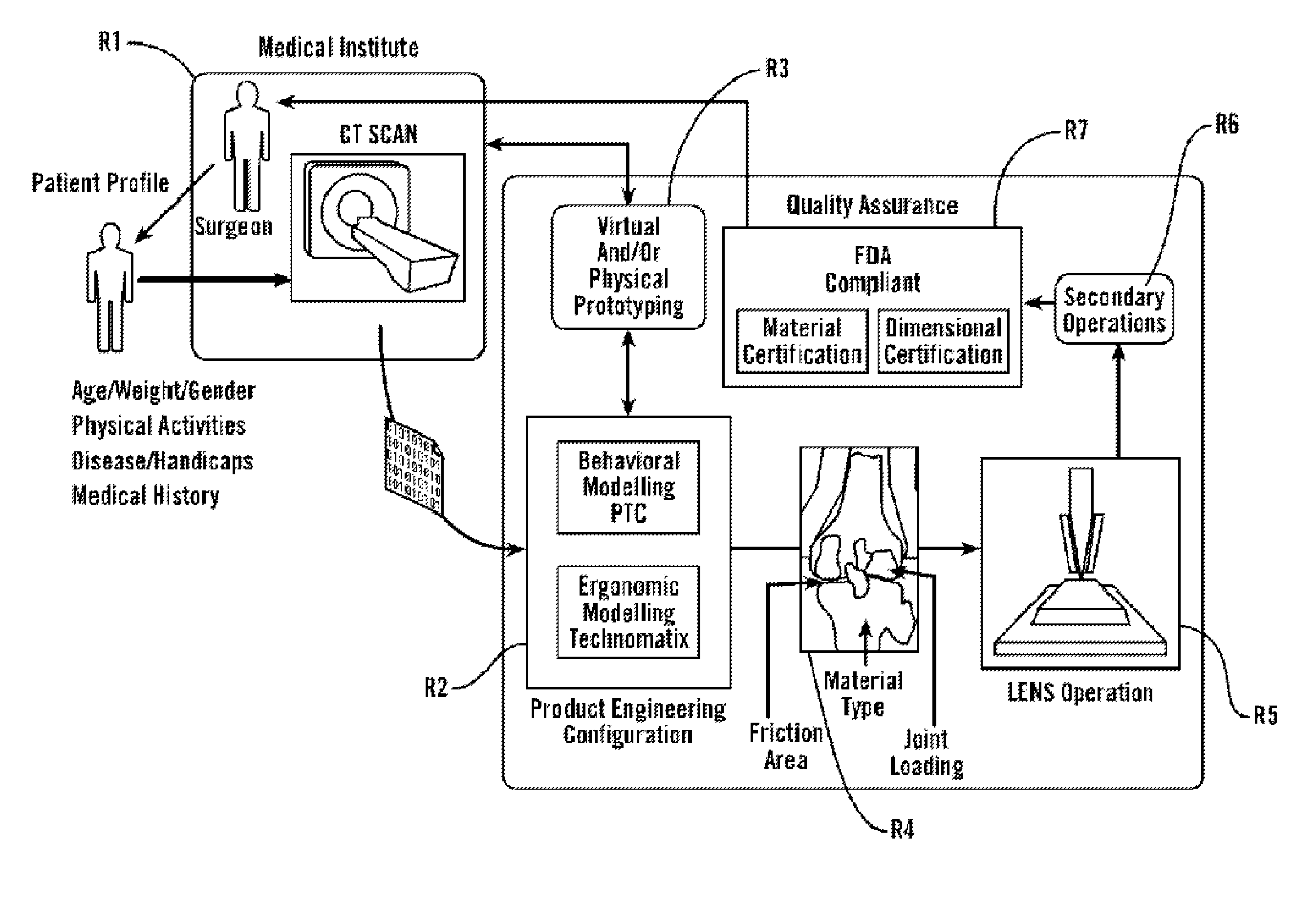
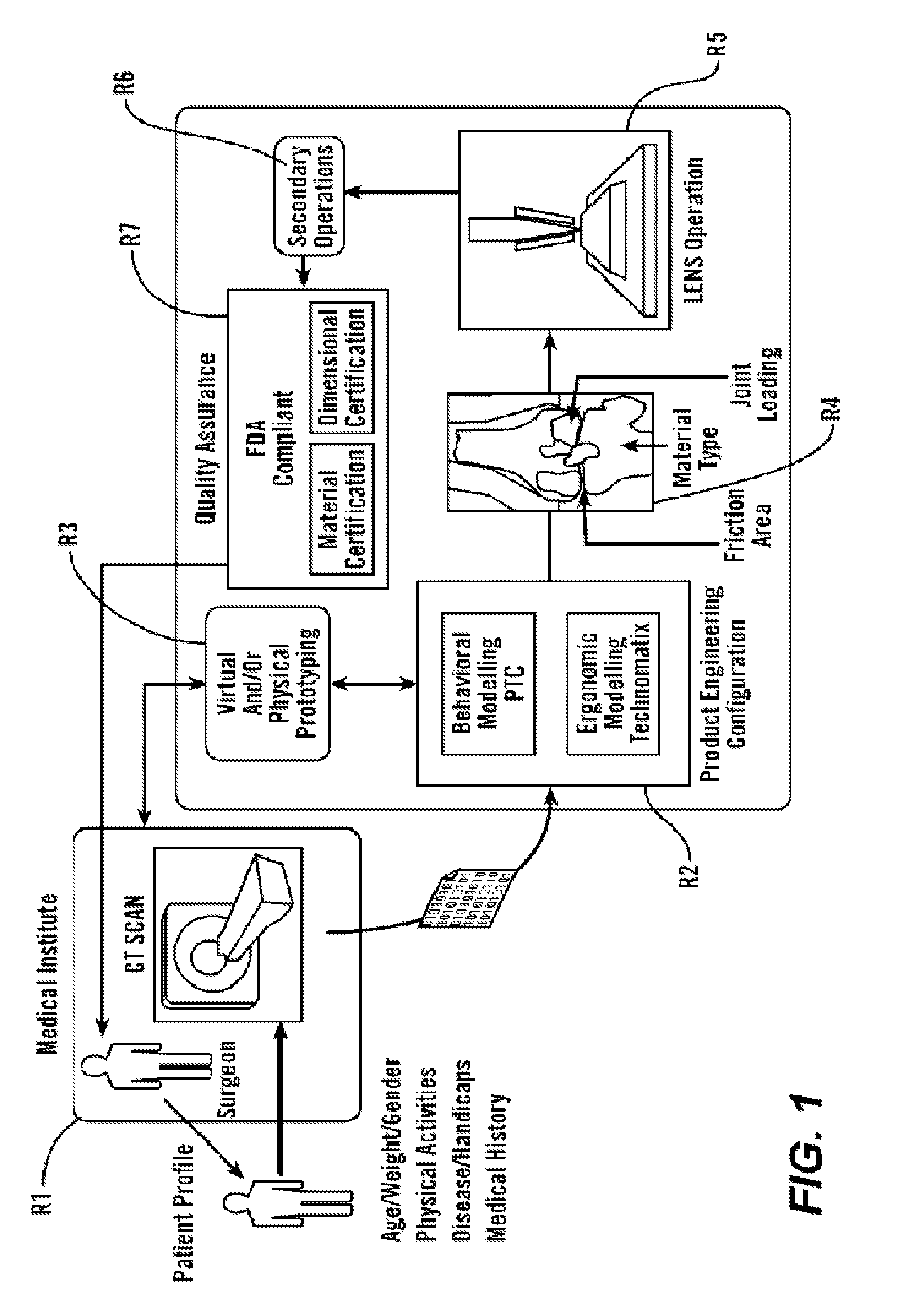
[0085]As shown in FIG. 1, in some embodiments, the present invention provides methods and tools to produce implantable medical devices that will precisely fit individual subjects. The present invention also comprises medical appliances and tools and implements designed and created through the disclosed process. In some embodiments, the invention is implemented through a combination of technologies including medical imaging (including CT, MRI, PET, X-ray, ultrasound, and others) and subject consultation (R1). Next, the product engineering configuration (R2) analysis is implemented using both behavioral modeling and ergonomic modeling analysis. Next, virtual and / or physical prototyping is performed (R3) which allows for validation of the product engineering results by further reference with (...

example i

Image Acquisition and Analysis

First Embodiment

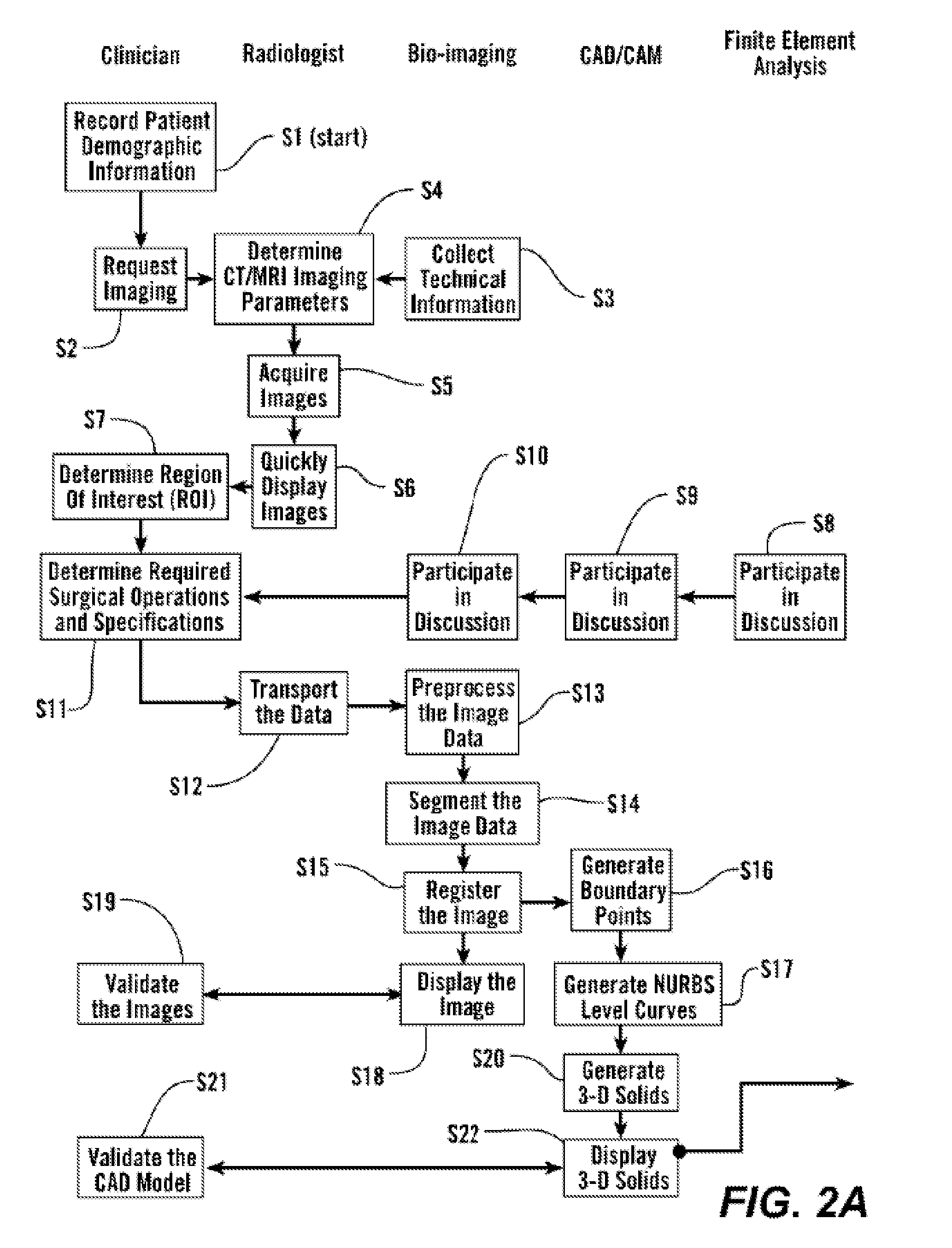
[0087]As shown in FIGS. 2A and 2B, in some embodiments, the process starts with step S1 where the subject's demographic information is recorded and the clinician makes a request for imaging, S2. 3-Dimensional image data is obtained from the subject S4 and presented for clinical evaluation with the cooperation of multiple specialists, S3 and using the invention described herein (FIGS. 1 and 2A). This uses multiple steps as listed in Table 1, and further elaborated below.

[0088]

TABLE 1Image Acquisition and Analysis1CT / MRI Image calibration2Calibration of laser surface contour scanning to determine surfacestructure as required for certain applications3Physical correlation of pixel data for precise reconstruction of thesubject's anatomical structure4In situ validation5Establish protocol for image acquisition and transport6Troubleshooting of various imaging parameters - SIze, intensity,orientation, spacing, etc.7Image file format, size, and tr...

example ii

Production

First Embodiment

[0111]In some embodiments, the design created above is produced using direct computer aided manufacturing (CAM) digital methods to produce the implant with laser-based additive free-form manufacturing as described above, S33. In some embodiments, production of each component is performed with the desired material or materials directly from powdered metals (and certain other materials) that are delivered to the desired spatial location and then laser annealed in place (using, for example, DMD, LENS or the like) or annealed using an electron beam (EBM). This produces a very high strength fine-grain structure, enables the production of internal features, enables layers of multiple materials, gradients of material properties, inclusion of ancillary internal elements, and produces resultant structures that generally require minimal post-production processing.

[0112]In some embodiments, multiple materials are applied sequentially, locally, and in specific location...


PUM


Abstract

The present invention provides methods, devices, systems, and instruments related to medical implants and surgical instruments produced to precisely fit individual subjects. In particular, the present invention utilizes a combination of medical imaging, quantitative image analysis, CAD, CAM, and additive manufacturing processes to personalized biocompatible devices.

Description

[0001]This application claims priority to U.S. Provisional Application No. 61 / 169,572 file Apr. 15, 2009, which is incorporated by reference in its entirety.FIELD OF THE INVENTION[0002]The present invention provides methods, devices, systems, and instruments related to medical implants and surgical instruments produced for personalized fit and / or personalized function of individual users. In particular, embodiments of the present invention utilize a combination of medical imaging; quantitative image analysis; computer aided design, manufacturing, and engineering; telemedicine; virtual design collaboration, virtual design simulation and validation; informatics; mass-customization production; and additive manufacturing processes to personalize biocompatible devices for fit and / or function. In some embodiments, a production system is statistically controlled enabling the repeatability of the system to be probabilistically forecasted and the accuracy of features produced for medical imp...

Claims


Application Information

Patent Timeline
Patent Type & Authority Patents(United States)
IPC IPC(8): G06F17/50
CPCA61F2/30G06F17/50G06F19/322G06F19/3437A61F2/2875A61F2/32A61F2002/30952A61F2002/30948B33Y80/00B33Y50/00B33Y70/00G16H50/50G16H10/60G06F30/00G06F30/20G06F2111/20G06F30/23
Inventor SCHROEDER, JAMES
Owner SCHROEDER JAMES
Why Eureka
Try Eureka