Arc-shaped cutting stitching instrument

A suturing device and an arc-shaped technology, applied in the field of arc-shaped cutting suturing devices, can solve the problems of staple resistance, small size, and incorrect formation of staples, and achieve the effects of good staple forming, convenient assembly and simple structure.

Active Publication Date: 2014-12-24
B J ZH F PANTHER MEDICAL EQUIP
View PDF6 Cites 12 Cited by
  • Summary
  • Abstract
  • Description
  • Claims
  • Application Information

AI Technical Summary

Problems solved by technology

[0005] However, the currently existing cutting and suturing devices all have a flat suturing surface, and the cutting size in the same space is small; when the surgical incision is long, when a suturing is completed, it often needs to be supplemented again to obtain a suitable suture length. , to ensure that the surgical incision is completely sutured
In addition, the blades of the cutting knife in the commonly used cutting and suturing devices are all parallel to the length direction of the suture line. The tissue that needs to be separated is cut. Since the thickness of the clamped tissue in the jaws may be inconsistent, it is easy to cause incomplete cutting in this way, and the operation is laborious.
At the same time, due to the large number of staples and the long suture size, the resistance encountered when the staples pass through the tissue is relatively large, especially the lower part of the staple cartridge assembly is prone to deflection, so that the staples cannot be formed correctly, and it is easy to cause bleeding at the suture port, resulting in failed operation
[0006] This shows that there are obvious deficiencies and defects in the structure and use of the stapler in the prior art, and it is urgent to be further improved.

Method used


Image

  • Arc-shaped cutting stitching instrument
  • Arc-shaped cutting stitching instrument
  • Arc-shaped cutting stitching instrument

Examples


Embodiment Construction

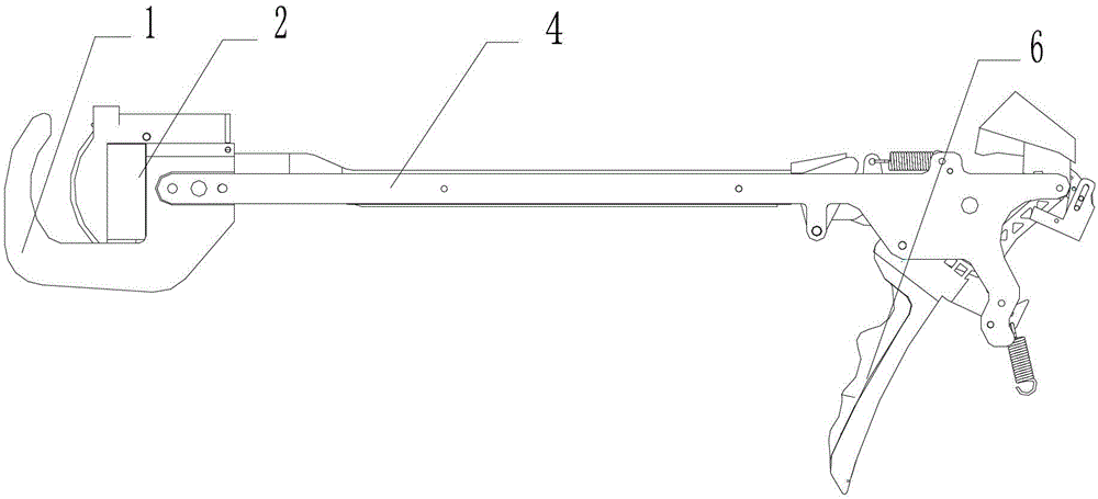
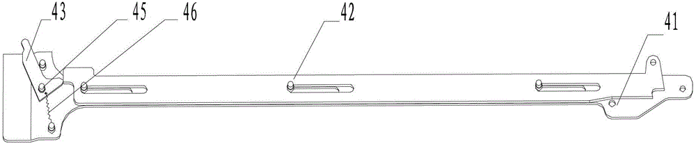
[0033] see figure 1 As shown, an arc-shaped cutting stapler of the present invention is based on the structure of the existing cutting stapler support plate, jaw support 1, staple cartridge assembly 2, nail abutment seat, connecting assembly 4, propulsion mechanism and firing mechanism 6 Above, design the surface of the staple anvil and the staple cartridge body of the staple cartridge assembly 2 as an arc, and design the connection and installation method among the bracket plate, component splint, and nail pusher plate as a matching structure between the chute and the pin, and in the assembly A cutting knife shifting block is installed at the front end of the splint to drive the cutting knife to move along the arc-shaped staple bin.

[0034] In order to describe the structural features of the present application more clearly, the direction of travel of the connecting assembly during the jaw closing process (i.e. figure 1 shown on the left) is "front" and its opposite directi...


PUM


Abstract

The invention relates to an arc-shaped cutting stitching instrument, which comprises a support plate, a jaw support, a staple bin assembly, a staple pressing seat, a connecting assembly, a propelling mechanism and a triggering mechanism, wherein the staple bin assembly comprises a staple bin and a cutter; the staple pressing seat and the staple bin are arc-shaped; the connecting assembly comprises a pair of assembly clamp plates, a staple pushing plate and a cutter shifting block; the staple pushing plate is arranged between the assembly clamp plates; the cutter shifting block is arranged at the front ends of the assembly clamp plates in a rotatable mode; each assembly clamp plate is provided with closed chutes; the staple pushing plate is provided with a triggering chute; the support plate is provided with a positioning pin; the assembly clamp plates and the staple pushing plate can be slidably arranged on the support plate in the front-back direction by matching the closed chutes, the triggering chute and the positioning pin; the top of the cutter shifting block is pressed against the bottom of the cutter; and the cutter shifting block can be pushed by the staple pushing plate to rotate, and then the cutter is driven to slide. The arc-shaped cutting stitching instrument has the advantages of small triggering force and good stitching staple forming effect, and the arc-shaped cutting stitching instrument is simple in structure and convenient to assemble, and is used safely.

Description

technical field [0001] The invention relates to the technical field of medical instruments, in particular to an arc cutting stapler. Background technique [0002] In medical surgery, since the first staple products appeared in the 1960s, medical staplers have become an indispensable medical device in the process of assisting incision suturing. Various surgical staplers are widely used in surgical operations to suture human digestive tract tissue, respiratory tract tissue and vascular tissue. The application of stapler can reduce operation time and improve operation quality. They are usually used for end-to-end, end-to-side and side-to-side suture operations such as esophagus, stomach, duodenum, small intestine, colon and rectum in the digestive tract, or hemorrhoidectomy and gastric pylorostomy to form channels or close incisions. It is used in the suturing of lungs, trachea and vascular tissues in the respiratory tract, especially for the suturing of organs and tissues th...

Claims


Application Information

Patent Timeline
Patent Type & Authority Patents(China)
IPC IPC(8): A61B17/115A61B17/072
CPCA61B2017/07221
Inventor 李学军刘青
Owner B J ZH F PANTHER MEDICAL EQUIP
Why Eureka
Try Eureka