Nail pushing sliding block of anastomat

A stapler and slider technology, applied in the field of medical devices, can solve the problems of reducing friction, increasing device firing force, increasing friction force, etc., and achieves the effects of simple structure, convenient manufacture and reduction of firing force

Pending Publication Date: 2022-03-22
SUZHOU MEIDONG HUICHENG PRECISION COMPONENTS CO LTD
View PDF0 Cites 0 Cited by
  • Summary
  • Abstract
  • Description
  • Claims
  • Application Information

AI Technical Summary

Problems solved by technology

In the process of matching the current pusher slider with the staple cartridge, there is a large friction force, which further increases the firing force of the instrument, which will affect the forming effect of the staple and the comfort of the surgeon
In the actual production and assembly process, dry powder lubricants are often sprayed onto the surfaces of the nail bins, nail magazines, nail pushers, and nail push sliders to reduce the friction coefficient during their movement and reduce their friction. However, dry powder lubricants are used in The staple magazine, staple pusher, staple magazine, and staple pusher slider form an ultra-thin grease-like film, which is easy to be damaged, and the friction between each other gradually increases as the movement progresses

Method used


Image

  • Nail pushing sliding block of anastomat
  • Nail pushing sliding block of anastomat
  • Nail pushing sliding block of anastomat

Examples


Embodiment 1

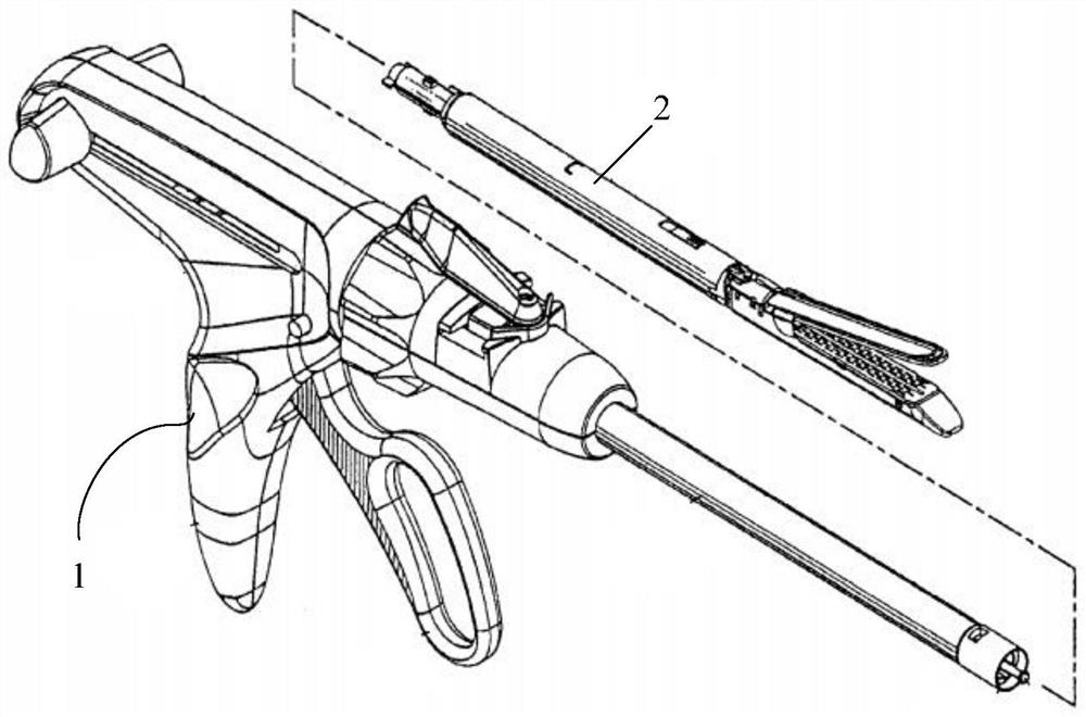
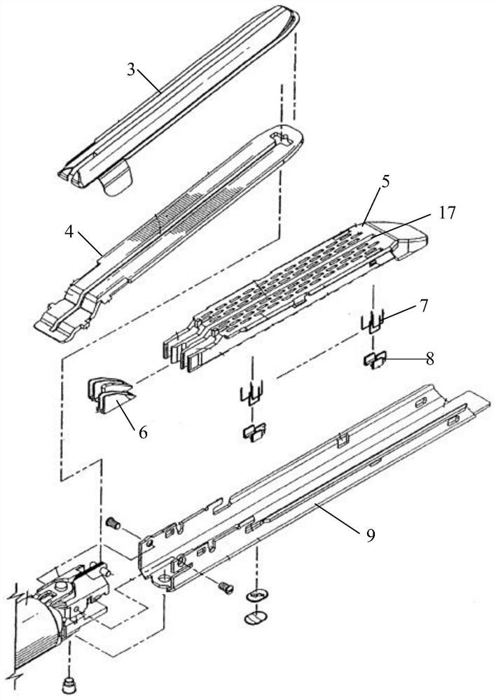
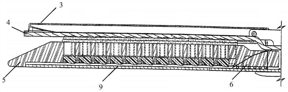
[0030] Figure 1-8 As shown, on the one hand, this embodiment discloses a stapler pusher slider, the bottom of the stapler slider 6 is provided with several cylindrical rollers 11 perpendicular to its moving direction, the rollers 11 and the stapler The inner surface of the nail box base 9 on the top is matched, and the nail pushing slider 6 has a working surface with a slope feature, and several cylindrical working rollers 10 are arranged on the working surface, and the working rollers 10 and the pushing nails on the stapler The lower end slope of the stapler 8 is matched, and the nail pushing slider 6 is also provided with a rolling module that matches the long groove 17 provided on the staple bin 5 on the stapler. When moving in the direction of the longitudinal axis, rolling friction occurs between the nail pushing slider 6 and the nail box base 9, and rolling friction occurs between the nail pushing slider 6 and the nail pushing device 8. Rolling friction occurs between ...

Embodiment 2

[0035] Figure 1-8 As shown, on the one hand, this embodiment discloses a stapler pusher slider, which is applied to a laparoscopic stapler. The bottom of the pusher slider 6 is provided with several cylindrical rollers 11 perpendicular to its moving direction. The roller 11 is matched with the inner surface of the nail box base 9 on the stapler, and the nail pushing slider 6 has a working surface with a slope feature, and several working rollers 10 are arranged on the working surface, and the working rollers 10 and the stapler The lower end slope of the nail pusher 8 on the stapler is matched with the lower end slope of the nail pusher 8, and a rolling module matching the long groove 17 provided on the staple bin 5 on the stapler is also provided on the nail pusher slider 6, and the nail pusher slider 6 is along the nail. When the longitudinal axis direction of the box base 9 moves, rolling friction occurs between the nail pushing slider 6 and the nail box base 9, rolling frict...


PUM


Abstract

A bottom rolling piece is selectively arranged at the bottom of the nail pushing sliding block in the direction perpendicular to the moving direction of the nail pushing sliding block, the bottom rolling piece is matched with the inner surface of a nail box base on the anastomat, a top rolling piece is selectively arranged on the working face of the nail pushing sliding block, and the top rolling piece is matched with the inclined face of the lower end of a nail pusher on the anastomat. A rolling module matched with a long groove formed in a nail bin of the anastomat is selectively arranged on the nail pushing sliding block, at least one of the bottom rolling piece, the top rolling piece and the rolling module is arranged, when the nail pushing sliding block moves in the longitudinal axis direction of the nail box base, rolling friction is generated between the nail pushing sliding block and the nail box base, rolling friction is generated between the nail pushing sliding block and the nail pusher, and the nail box base and the nail pusher can move in the longitudinal axis direction of the nail box base. Rolling friction is generated between the nail pushing sliding block and the inner side wall of the long groove. The friction force between the nail pushing sliding block and the nail box base, the nail bin and the nail pusher is reduced in a rolling mode, the percussion force of instruments is reduced, the structure is simple, manufacturing is convenient, and the nail pushing device is used for linear cutting, laparoscopic cutting anastomats and the like.

Description

technical field [0001] The invention belongs to the technical field of medical devices, and in particular relates to a stapler pushing slider. Background technique [0002] Stapler is a device used in medicine to replace manual suturing. Its main working principle is to use titanium nails to separate or anastomose tissues, similar to a stapler. The current staplers mainly include the following categories: skin staplers, digestive tract (esophagus, gastrointestinal, etc.) circular staplers, rectal staplers, circular hemorrhoid staplers, and endoscopic staplers. [0003] The staple magazine in the current stapler is provided with a staple push-out mechanism. The staple push-out mechanism includes a staple pusher slider and a staple pusher, and an inclined surface is arranged on the staple pusher slider to match the smooth surface at the bottom of the staple pusher. Contact, the staple pusher moves slowly along the slope on the staple pusher slider, and the staples are pushed ...

Claims


Application Information

Patent Timeline
Patent Type & Authority Applications(China)
IPC IPC(8): A61B17/072
CPCA61B17/072A61B2017/07257A61B2017/07271A61B2017/07278
Inventor 刘子贤张林马世涛刘子德
Owner SUZHOU MEIDONG HUICHENG PRECISION COMPONENTS CO LTD
Why Eureka
Try Eureka