End effector and linear anastomat

An end effector and stapler technology, applied in the field of medical devices, can solve the problems of large firing force, poor nailing effect, tissue leakage, etc., and achieve the effect of saving the firing force, improving the nailing effect, and avoiding deformation.

Pending Publication Date: 2020-12-01
SUZHOU YINGTUKANG MEDICAL TECH CO LTD
View PDF0 Cites 0 Cited by
  • Summary
  • Abstract
  • Description
  • Claims
  • Application Information

AI Technical Summary

Problems solved by technology

[0003] The staple forming method of the existing linear stapler is often to push the staple seat through the transmission device to push out all the staples at one time and fire them into staples, so that the staples are prone to large and small ends and dovetails, and the staple forming effect is poor, resulting in The stitching effect is not good and at the same time it will cause waste
Moreover, due to the one-time firing of a large number of staples, some of the staples cannot be sutured firmly, which will cause tissue leakage and other situations; at the same time, because one-time firing is required, the firing force is relatively large, and the cantilever beam will be damaged after multiple firings. The anvil of the structure deforms

Method used


Image

  • End effector and linear anastomat
  • End effector and linear anastomat
  • End effector and linear anastomat

Examples


Embodiment 1

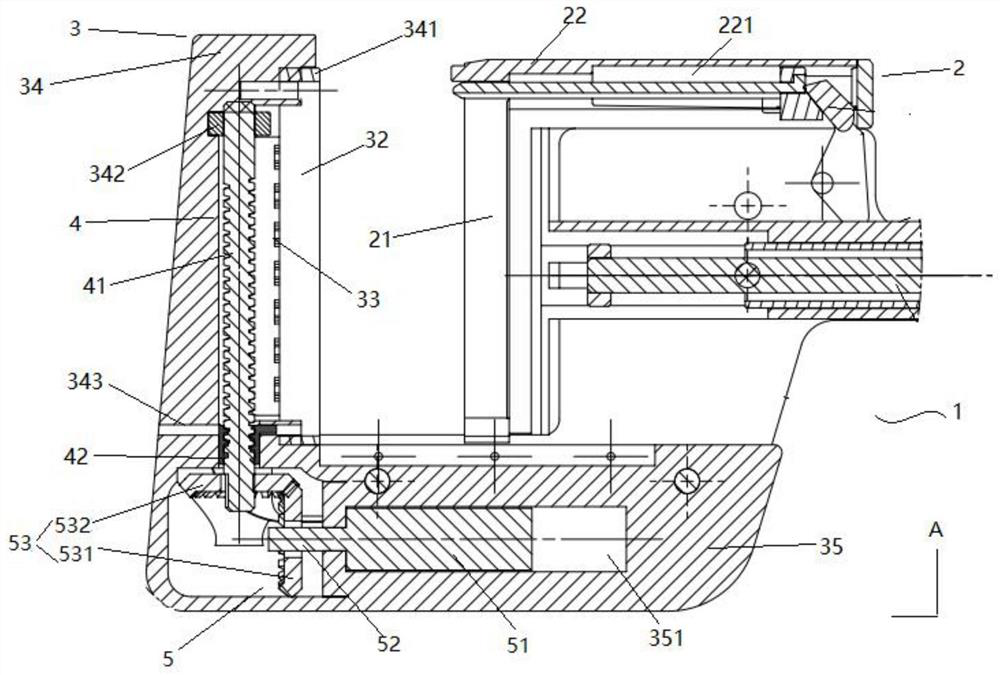
[0042] See figure 1 The end effector 1 shown in the first embodiment includes a nail anvil assembly 2 and a staple cartridge assembly 3, the staple cartridge assembly 3 includes a staple cartridge 32 for accommodating staples, and the nail anvil assembly 2 includes a Cooperating nail anvil 21. The end effector 1 of the present invention can make staples into staples sequentially. Specifically, the end effector 1 also includes a pusher assembly 4 for pushing the staples to move toward the anvil 21, and a pusher assembly 4 for driving the staples. Assembly 4 sequentially fires staples into staple firing assembly 5 .

[0043] In this embodiment, the nail pusher assembly 4 includes a screw rod 41 disposed on the nail cartridge assembly 3 and a firing nut 42 sleeved on the screw rod 41, defining the axial direction of the screw rod 41 and the firing nut 42 as the first axial direction ( figure 1 The direction of the straight line where the middle arrow A is located). The firing ...

Embodiment 2

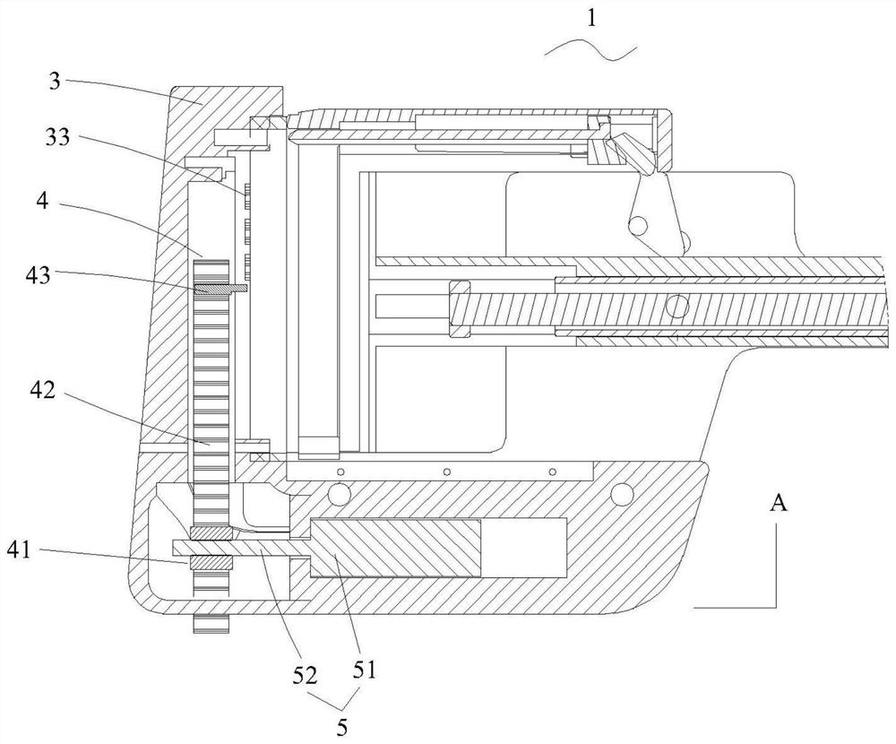
[0047] See figure 2 , the structure of the end effector shown in the second embodiment is basically the same as that shown in the first embodiment, the difference is that the pusher assembly 4 and the firing assembly 5 of the two are of different structures.

[0048] In this embodiment, the nail pusher assembly 4 includes a driving wheel 41 arranged on the nail cartridge assembly 3, a driven wheel 42, an endless belt 43 sleeved on the driving wheel 41 and the driven wheel 42, and a pusher wheel arranged on the endless belt. The nail bar 44 defines the axis direction perpendicular to the driving wheel 41 and the driven wheel 42 as the first axis direction ( figure 2 The direction of the straight line where the middle arrow A is located). The firing assembly 5 is connected to drive the drive wheel 41 to rotate, so that the endless belt 43 drives the push rod 44 to move along the first axis. The firing assembly 5 includes a firing motor 51 and a firing input shaft 52 arranged...

Embodiment 3

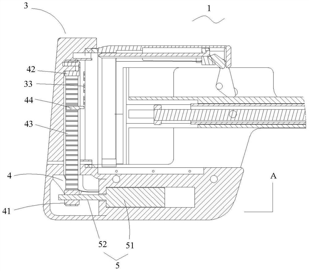
[0050] See image 3 , the structure of the end effector 1 shown in the third embodiment is basically the same as that shown in the first embodiment. The pusher rack 41 arranged on the nail cartridge assembly 3, the pusher gear 42 meshed with the pusher rack 41 and the pusher rod 43 arranged on the pusher rack 41 define an axis perpendicular to the pusher gear 42 The direction is the direction of the first axis ( image 3 The direction of the straight line where the middle arrow A is located). When the firing motor 51 in the firing assembly 5 works, the firing input shaft 52 on the firing motor 51 drives the pusher gear 42 to rotate, so that the pusher rack 41 drives the pusher rod 43 on it to move in the first axis direction , so that the pusher rod 43 triggers the pusher piece 33 to sequentially strike the staples therein.


PUM


Abstract

According to the end executor and the linear anastomat, by arranging the nail pushing assembly and the percussion assembly, when the end executor is closed, the percussion assembly drives the nail pushing assembly to move, so that suturing nails in the nail bin are sequentially percussed, and the problems of large heads, small heads, dovetail and the like are solved. Therefore, the end executor and the linear anastomat adopt a sequential nailing mode, the required percussion force can be saved, the nail anvil is prevented from deforming, and a good nailing effect, a good suturing effect and good surgical safety are achieved.

Description

technical field [0001] The invention relates to an end effector and a linear stapler, belonging to the field of medical instruments. Background technique [0002] Linear stapler, also known as alimentary canal closure device, is a device that can insert multiple interlaced staples in a straight line on the tissue, and is also one of the devices widely used to replace manual linear suture. It is mainly used to suture the stumps of the stomach, duodenum, small intestine, and colon, and it is a full-thickness eversion suture. [0003] The staple forming method of the existing linear stapler is often to push the staple seat through the transmission device to push all the staples out at one time and fire them into staples, so that the staples are prone to large and small ends and dovetails, and the staple forming effect is poor, resulting in The sewing effect is not good, and it will cause waste at the same time. Moreover, due to the one-time firing of a large number of staples...

Claims


Application Information

Patent Timeline
Patent Type & Authority Applications(China)
IPC IPC(8): A61B17/072
CPCA61B17/07207A61B2017/00398A61B2017/07271
Inventor 徐荣华张翚杜运峰刘殿臣
Owner SUZHOU YINGTUKANG MEDICAL TECH CO LTD
Why Eureka
Try Eureka