
Cleaning system, cleaning device, and method of using cleaning device

一种清洗装置、入口的技术,应用在使用液体的清洁方法、清洁方法和用具、化学仪器和方法等方向,能够解决管路阻塞、弯管P3阻塞等问题

Active Publication Date: 2013-02-06
VISERA TECH CO LTD
View PDF7 Cites 2 Cited by
  • Summary
  • Abstract
  • Description
  • Claims
  • Application Information

AI Technical Summary

Problems solved by technology

However, the photoresist may still produce crystallization and precipitation in the elbow P3, which will cause the blockage of the elbow P3 in the region R2
[0004] In view of this, the present invention provides a cleaning device for process equipment to improve the blockage problem in the aforementioned pipeline

Method used


Image

  • Cleaning system, cleaning device, and method of using cleaning device
  • Cleaning system, cleaning device, and method of using cleaning device
  • Cleaning system, cleaning device, and method of using cleaning device

Examples


Embodiment Construction

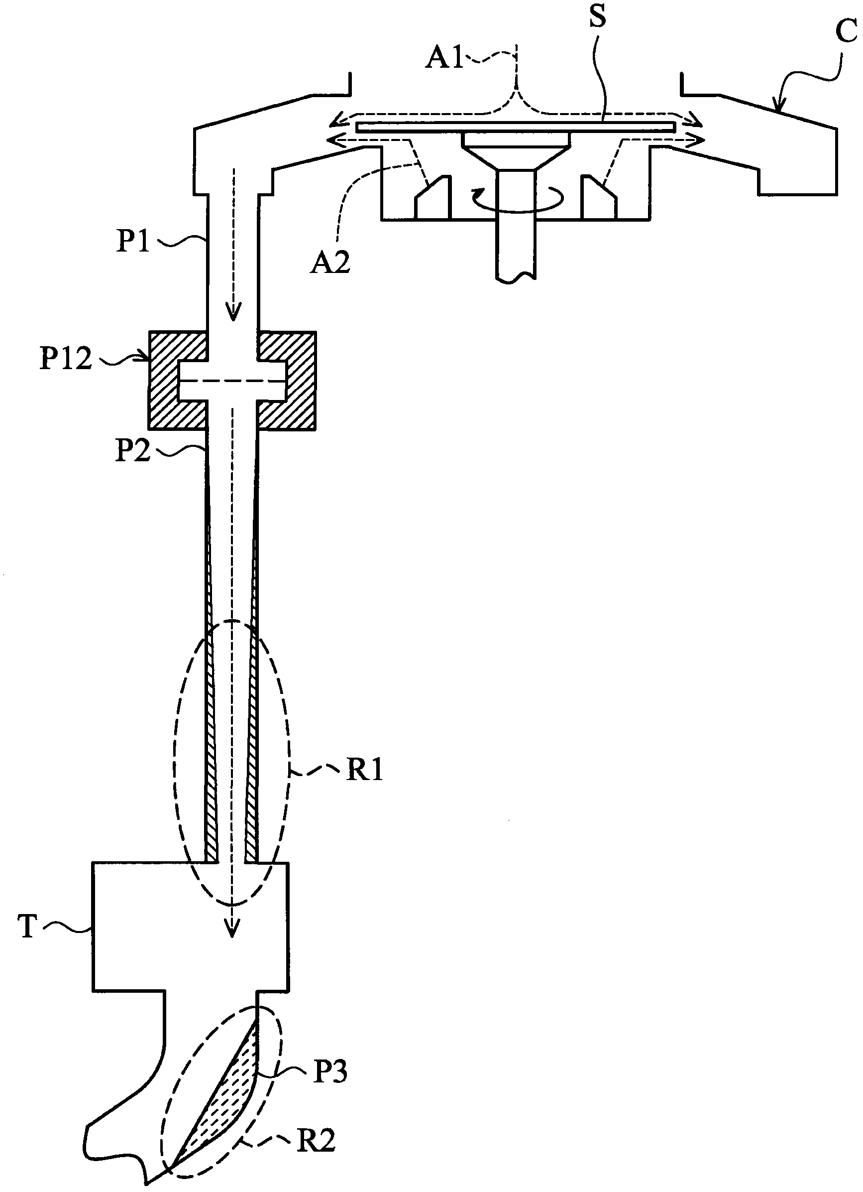
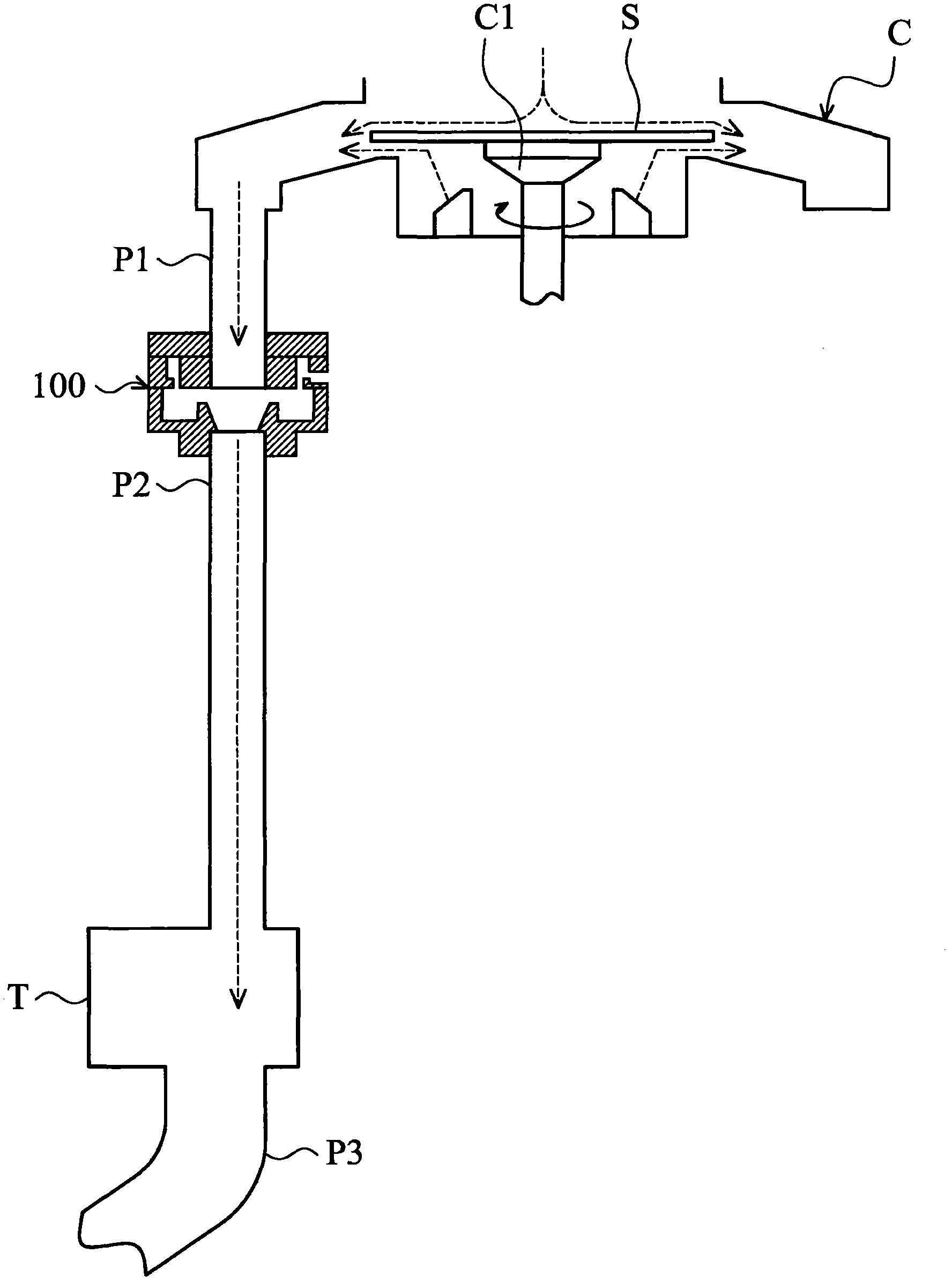
[0058] Please refer to figure 2 , the cleaning device 100 of an embodiment of the present invention is connected to the discharge pipe P1 and the liquid discharge pipe P2 of the spin coating equipment C, wherein the aforementioned cleaning device 100 can be connected with figure 1 The pipe clamp device P12 in is installed at the same position, but its installation position is not limited thereto. In a semiconductor process, such as a photolithography process, a substrate S is mounted on the chuck C1 of a spin coating device C. When the substrate S starts to rotate, it contains photoresist and cleaning agent (such as photoresist thinner). ) will be washed away from the surface of the substrate S and discharged through the discharge pipe P1. In this embodiment, the aforementioned fluid flows from the cleaning device 100 into the drain tank T through the drain pipe P2, and the discharged liquid flows into the pipeline equipment system (not shown) sequentially through the elbow ...


PUM


Abstract

The invention provides a cleaning system, a cleaning device, and a method of using the cleaning device. The cleaning device is provided, including a top portion, a middle portion, and a bottom portion. The top portion includes a first opening. The middle portion is connected to the top portion, and includes an inlet on a lateral side, an annular channel communicated with the inlet, and a second opening communicated with the first opening. The bottom portion is connected to the middle portion, and includes a reservoir and a third opening. The third opening communicates the second opening and the reservoir.

Description

technical field [0001] The present invention relates to a cleaning device, in particular to a cleaning device provided for process equipment (processing equipment), wherein the aforementioned process equipment also uses a process liquid. Background technique [0002] Conventional process equipment, such as spin coating equipment, typically contains many lines that conduct process fluids. figure 1 Shows a known spin coating device C connected to the drain pipe P2 and the drain pipe P1. In a semiconductor process such as a photolithography process, a substrate S can be mounted on the chuck of the spin coating device C. Such as figure 1 As shown by the arrows A1 and A2 in the figure, when the substrate S starts to rotate, the fluid containing photoresist and cleaning agent (such as photoresist thinner) will be washed away from the surface of the substrate S, and will be discharged from the spin coating through the discharge pipe P1. Cloth device C. [0003] In general, the d...

Claims


Application Information

Patent Timeline
Patent Type & Authority Applications(China)
IPC IPC(8): B08B9/22
CPCB08B3/08H01L21/67017B08B9/22B08B3/04B05D1/005H01L21/02282H01L21/67051B08B9/027
Inventor 彭彦韶薛家皓邓国星
Owner VISERA TECH CO LTD
Features
  • Generate Ideas
  • Intellectual Property
  • Life Sciences
  • Materials
  • Tech Scout
  • Unparalleled Data Quality
  • Higher Quality Content
  • 60% Fewer Hallucinations
Learn More