Torque tool

A tool and torque technology, applied in the field of corner wrench/torque wrench, to avoid the danger of confusion, prevent mechanical damage, and reduce costs

Inactive Publication Date: 2013-02-06
HAZET WERK HERMANN ZERVER
View PDF7 Cites 0 Cited by
  • Summary
  • Abstract
  • Description
  • Claims
  • Application Information

AI Technical Summary

Problems solved by technology

[0012] Against this background, in particular the adjustment of the display elements of the torque tool leaves room for improvement

Method used


Image

  • Torque tool
  • Torque tool
  • Torque tool

Examples


Embodiment Construction

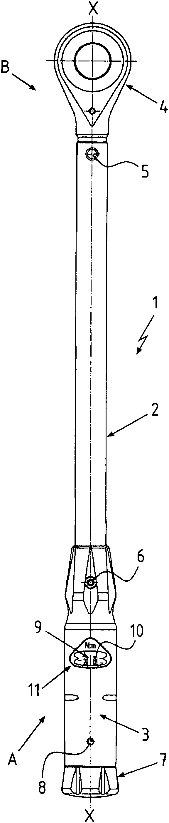
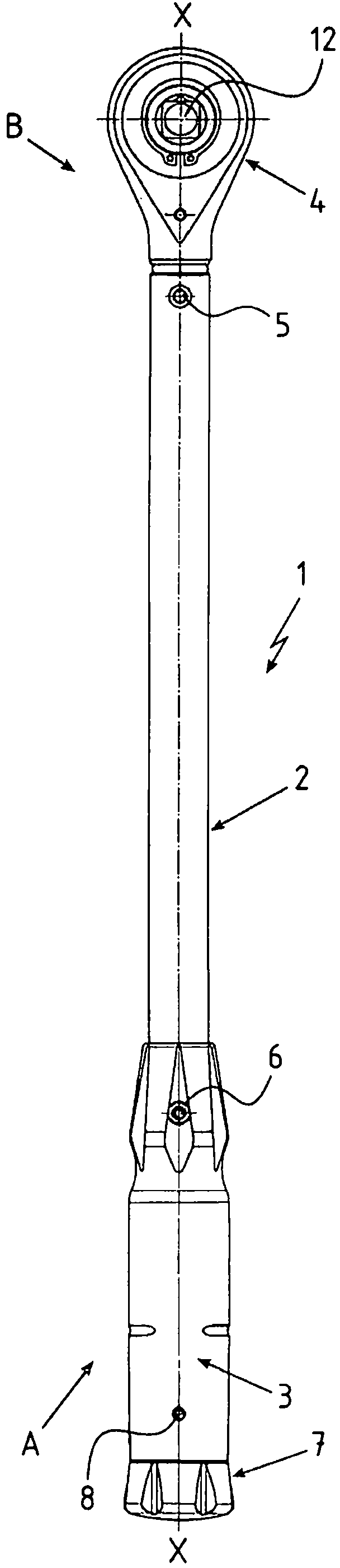
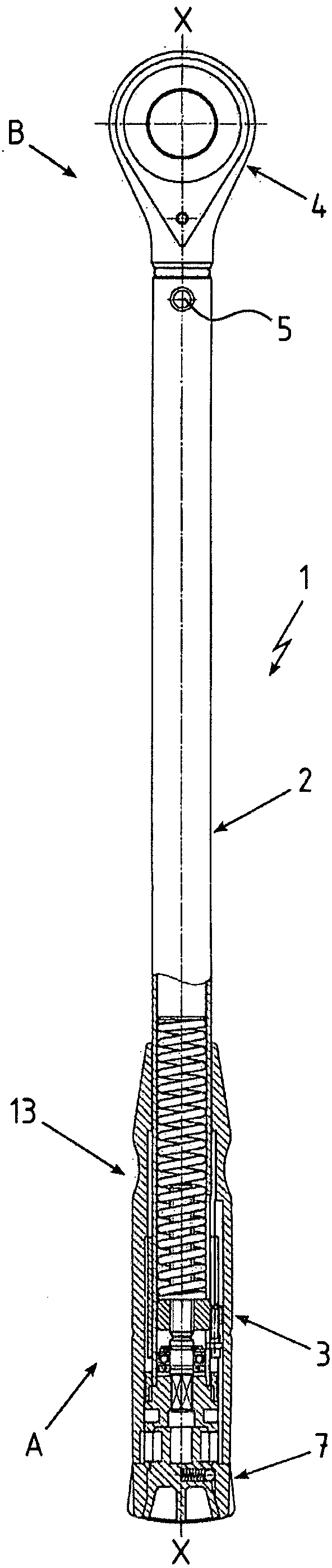
[0048] figure 1 A torque tool 1 according to the invention is shown having a tool shaft 2 and a handle 3 arranged on an end section A of the tool shaft 2 . A tool head 4 is arranged on the end section B of the tool shaft 2 opposite the handle 3 . The tool bit 4 leads into a shank, not shown in detail here, by means of which the tool bit 4 is inserted into the end section B of the tool shaft 2 and secured by a cotter pin 5 . In principle the cotter pin 5 can also be a detachable connecting element.

[0049] The handle 3 is fastened to the end section A of the tool shaft 2 via a connecting element 6 . An adjusting knob 7 is arranged on the free end of the handle 3 . The adjusting knob 7 is mounted rotatably about the longitudinal direction X of the tool shaft 2 inside the handle 3 and is prevented from being pulled out of the handle 3 by means of the connecting element 8 . In the central area of ​​the handle 3 is arranged a display element 9 by means of which the correspondi...


PUM


Abstract

The present invention relates to a torque tool which comprises a tool shank (2) and a hand grip (3) arranged in an end section (A) of the tool shank (2). A clamping unit (13) is arranged inside the hand grip (3) and/or the tool shank (2), on which respective release torque is adjustable. The clamping unit (13) comprises a displaceable spindle nut (16) in longitudinal direction (X) of the tool shank, and a spindle. The spindle has external threads, and the spindle nut (16) is engaged with the external threads via corresponding internal threads. The spindle nut (16) is at least indirectly coupled with a display medium. Adjusted release torque is displayed via the display medium. The spindle nut (16) is coupled with the display medium via a control unit (18). The relative position of the spindle nut and the display medium is changed to each other via the control unit (18) in longitudinal direction (X).

Description

technical field [0001] The invention relates to a torque tool, in particular an angle wrench / torque wrench, according to the features of the preamble of claim 1 . Background technique [0002] Threaded connections require a defined tightening torque to ensure a reliable and durable connection of components. In order to transmit the required torque, a special screw tool is used as a torque tool in the form of an angle wrench or a torque wrench. and / or acoustic signals. [0003] For this purpose, the torque tool has, in most cases, a tensioning unit arranged on the inside, by means of which the transmittable tightening torque can be adjusted. The tensioning unit includes a spring-loadable release mechanism for this purpose. When the release torque is reached, the release mechanism usually withdraws the previously set spring force abruptly, for example by pivoting. The helical spring required for this is arranged between the release mechanism and the spindle nut. Through t...

Claims


Application Information

Patent Timeline
Patent Type & Authority Applications(China)
IPC IPC(8): B25B23/142
CPCB25B23/1427
Inventor T·拜尔特
Owner HAZET WERK HERMANN ZERVER
Why Eureka
Try Eureka