Eureka AIR delivers breakthrough ideas for toughest innovation challenges, trusted by R&D personnel around the world.
Stretch-bending straightener
What is Al technical title?
Al technical title is built by PatSnap Al team. It summarizes the technical point description of the patent document.
A technology of stretching, bending, straightening and equipment, which is applied in the direction of metal processing equipment, manufacturing tools, rolling mill control devices, etc., to achieve the effect of eliminating residual waviness
Inactive Publication Date: 2013-03-13
瑞戴克斯股份有限公司
View PDF9 Cites 4 Cited by
Summary
Abstract
Description
Claims
Application Information
AI Technical Summary
This helps you quickly interpret patents by identifying the three key elements:
Problems solved by technology
Method used
Benefits of technology
Problems solved by technology
[0007] The stretch-bending straightening devices known in practice, in which elastically acting deflection rollers are also provided if necessary, have proven to be effective in principle, but they require further improvement
Method used
Image
Click on the blue label to locate the original text in one second.
Reading with bidirectional positioning of images and text.
Examples
Embodiment Construction
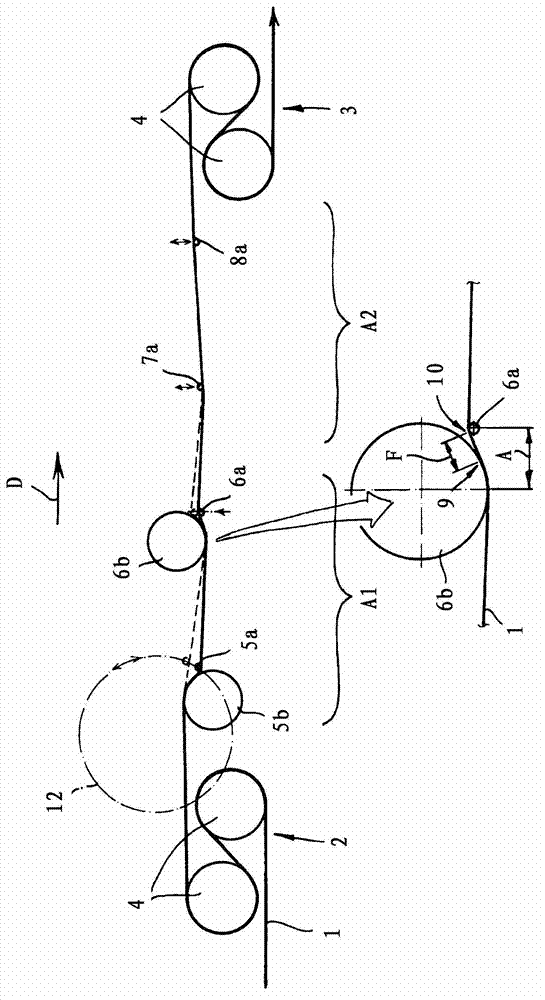
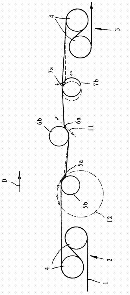
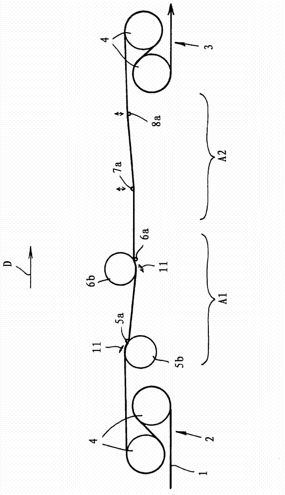
[0031] The figures each show a stretch-bend straightening device for stretch-bend straightening of a metal strip 1 . This stretch-bending straightening device has in its basic structure an entry pinch roll set 2 and an exit pinch roll set 3 as well as straightening rolls 5 a , 6 a arranged between said pinch roll sets 2 , 3 , 7a, 8a. The entry pinch roll set 2 with pinch rolls 4 can be designed as a braking roll set, while the exit pinch roll set 3 with pinch rolls 4 can be designed as a tension roll set. The strip travel direction D extends horizontally or substantially horizontally.
[0032] Tensile stresses can be generated in the metal strip 1 by means of the set of clamping rollers 2 , 3 , but are less than the elastic limit of the strip material. The strip is bent alternately in the plastic or elastoplastic range around the straightening rollers 5 a to 8 a and is then stretched plastically and thus elongated. In this case, each straightening roller 5 a , 6 a , 7 a , 8...
PUM
Property
Measurement
Unit
diameter
aaaaa
aaaaa
diameter
aaaaa
aaaaa
Abstract
The invention relates to a method and stretch-bending straightener for straightening metal strips (1) by stretch-bending, comprising a plurality of straightening rolls (5a, 6a, 7a, 8a) which are arranged behind one another in the strip flow direction (D) and spaced from one another in the strip flow direction (D), wherein the strip (1) subject to tensile stress below the limit of elasticity is alternately bent around the straightening rolls (5a, 6a, 7a, 8a), undergoing plastic elongation, wherein a deflecting roll (5b, 6b, 7b) is arranged upstream of one or more straightening rolls (5a, 6a, 7a), respectively, wherein said straightening rolls can be adjusted relative to the strip (1) and wherein said deflecting roll has a larger diameter than the respective downstream straightening roll. Said method and said system are characterized in that, in order to vary the immersion depth, the straightening rolls (5a, 6a, 7a) can be adjusted relative to the associated deflecting roll (5b, 6b, 7a) such that the free strip length (F) between the run-off point (9) of the strip (1) from the deflecting roll to the run-on point (10) of the strip (1) onto the associated straightening roll does not exceed a predefined maximum value, above which longitudinal undulations of the strip form. The system is preferably designed such that, as the immersion depth and / or the angle of contact are varied, the free strip length never exceeds the maximum value over the entire adjusting range.
Description
technical field [0001] The present invention relates to a method and an apparatus for stretching, bending and straightening metal strip, which has a plurality of (horizontal or substantially horizontal) strip running direction arranged one behind the other and spaced apart in the strip running direction. Straightening rollers around which the strip in a tensile stress less than the elastic limit is alternately bent and plastically stretched at this time, in one or more straightening rollers which can be adjusted relative to the strip In each case a deflection roller is arranged upstream, which has a larger diameter than the corresponding downstream straightening roller. Background technique [0002] During stretch bend leveling in such stretch bend leveling equipment or such stretch bend leveling stands, the strip is usually under a tensile stress which is less than the elastic limit or yield limit and the strip surrounds the straightening rollers Alternately bent in the pl...
Claims
Application Information
Patent Timeline
Application Date:The date an application was filed.
Publication Date:The date a patent or application was officially published.
First Publication Date:The earliest publication date of a patent with the same application number.
Issue Date:Publication date of the patent grant document.
PCT Entry Date:The Entry date of PCT National Phase.
Estimated Expiry Date:The statutory expiry date of a patent right according to the Patent Law, and it is the longest term of protection that the patent right can achieve without the termination of the patent right due to other reasons(Term extension factor has been taken into account ).
Invalid Date:Actual expiry date is based on effective date or publication date of legal transaction data of invalid patent.