Bonding process of solar condenser lens assembly

A solar concentrating and lens assembly technology, applied in solar thermal energy, solar thermal power generation, solar thermal collectors, etc., can solve the problems of short service life of glue, poor bonding effect, low impact resistance, etc., and achieve firm bonding performance , The effect of strong bonding firmness and stable bonding performance

Inactive Publication Date: 2013-03-27
DALIAN GREAT OCEAN NEW ENERGY DEV
View PDF3 Cites 7 Cited by
  • Summary
  • Abstract
  • Description
  • Claims
  • Application Information

AI Technical Summary

Problems solved by technology

[0002] The solar concentrating system is a device used to absorb and collect solar energy in the solar thermal utilization system. It is the key to affecting the efficiency of solar energy utilization. Its core component is the concentrating lens assembly. The existing concentrating lens assembly usually uses several A small piece of plastic lens is fixed to the plastic back plate to form a parabolic structure. The plastic lens and the plastic back plate have poor aging resistance and low impact resistance, which cannot meet the needs of long-term outdoor operation; Light effect, reflection efficiency is difficult to achieve a high index, and the surface of the reflective film is easy to be scratched, easy to attenuate and degrade; now there are some realization methods of concentrating lens components that use double-sided tape or glue to bond the lens and the back plate, but The adhesion between the lens and the back plate is poor, the service life of the glue is short, the bonding process is not uniform, the bonding effect is poor, the operation is complicated, and the full contact between the lens and the back plate cannot be realized, so the impact resistance of the lens cannot be guaranteed. Ability and Environmental Adaptability

Method used


Image

  • Bonding process of solar condenser lens assembly
  • Bonding process of solar condenser lens assembly
  • Bonding process of solar condenser lens assembly

Examples


Embodiment Construction

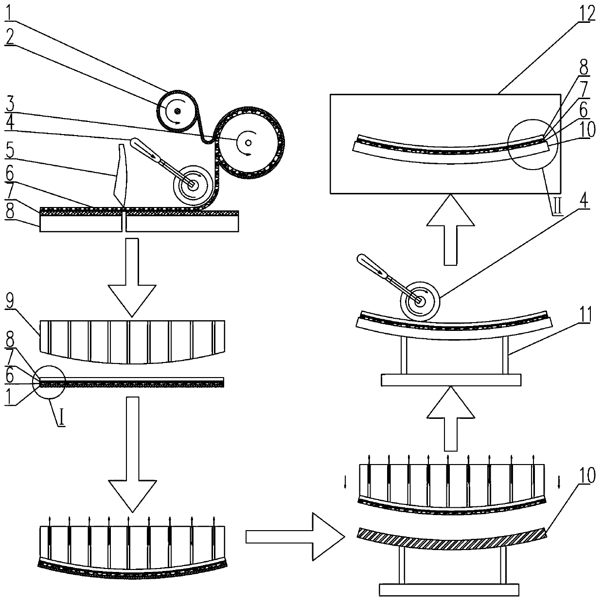
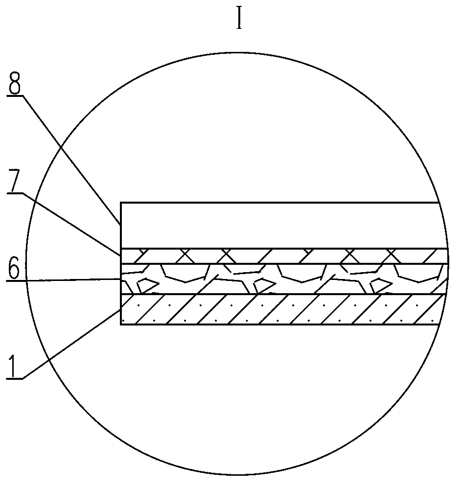
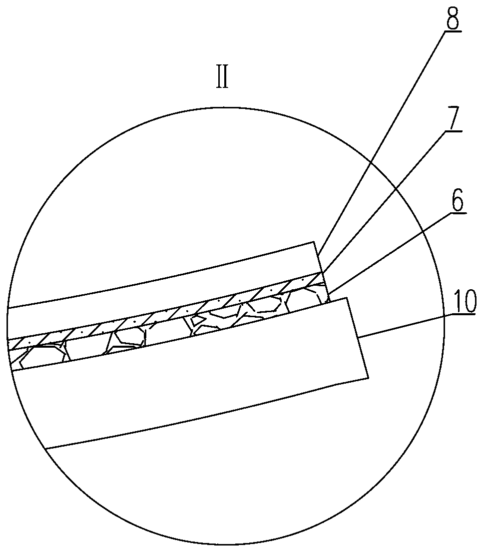
[0023] Such as figure 1 , figure 2 and image 3 A bonding process for a solar concentrating lens assembly shown, comprising the steps of:

[0024] Step 1: After cleaning and drying, the lenses divided according to certain specifications are tiled on the operation platform or the conveyor belt of the assembly line according to the paint surface facing upwards and a certain distance between the lenses;

[0025] Step 2: Align one end of the pressure-sensitive adhesive film with one end of the lens, and glue the lower surface of the pressure-sensitive adhesive film to the paint surface of the lens; rotate the roller of the pressure-sensitive adhesive tape and use the elastic push roller to gradually push the pressure-sensitive adhesive film to the other end of the lens, and at the same time The release paper on the lower surface of the pressure-sensitive adhesive film is driven to rotate by the release paper recovery roller;

[0026] Step 3: Cut and separate the pressure-sensi...


PUM


Abstract

The invention discloses a bonding process of a solar condenser lens assembly. The bonding process comprises the following steps of enabling one ends of pressure-sensitive adhesive films to align with one ends of lenses, and bonding the painting surfaces of the lenses to the lower surfaces of the pressure-sensitive adhesive films; rotating a pressure-sensitive adhesive tape roller, utilizing an elastic push roller to push the pressure-sensitive adhesive films to the other ends of the lenses, and enabling a release paper recycling roller to drive release paper on the lower surfaces of the pressure-sensitive adhesive films to rotate; cutting and separating the pressure-sensitive adhesive films matched with the lenses according to the dimensions of cut lenses; respectively enabling a plurality of glass surfaces of the cut lenses to be adsorbed and flatly attached onto an adsorption surface of a convex die; removing the release paper on the upper surfaces of the pressure-sensitive adhesive films, and attaching the convex die adsorbing the plurality of cut lenses onto a back plate, wherein two ends of the convex die align with two ends of the back plate; and taking off the convex die, and utilizing the elastic push roller to gradually push the glass surfaces of the lenses to enable the upper surfaces of the pressure-sensitive adhesive films to completely contact with the bonding surface of the back plate. By means of the bonding process of the solar condenser lens assembly, the bonding effect is good, and the bonding performance is stable. Furthermore, the bonding process can be widely applied to the field of production of the solar condenser lens assembly.

Description

technical field [0001] The invention relates to a bonding process of a solar concentrating lens assembly. Background technique [0002] The solar concentrating system is a device used to absorb and collect solar energy in the solar thermal utilization system. It is the key to affecting the efficiency of solar energy utilization. Its core component is the concentrating lens assembly. The existing concentrating lens assembly usually uses several A small piece of plastic lens is fixed to the plastic back plate to form a parabolic structure. The plastic lens and the plastic back plate have poor aging resistance and low impact resistance, which cannot meet the needs of long-term outdoor operation; Light effect, reflection efficiency is difficult to achieve a high index, and the surface of the reflective film is easy to be scratched, easy to attenuate and degrade; now there are some realization methods of concentrating lens components that use double-sided tape or glue to bond the...

Claims


Application Information

Patent Timeline
Patent Type & Authority Applications(China)
IPC IPC(8): G02B7/182
CPCF24S23/74F24S23/82Y02E10/40
Inventor 阿古达木王振声
Owner DALIAN GREAT OCEAN NEW ENERGY DEV
Why Eureka
Try Eureka