Friction-free rotary air supply air flotation device

A rotary air supply, frictionless technology, applied in the directions of bearings, shafts and bearings, mechanical equipment, etc., can solve problems such as the influence of thrust bearing motion, and achieve the effect of continuous air supply

Active Publication Date: 2015-02-25
铜陵汇恒电子科技有限公司
View PDF8 Cites 0 Cited by
  • Summary
  • Abstract
  • Description
  • Claims
  • Application Information

AI Technical Summary

Problems solved by technology

[0004] In order to solve the deficiencies of the influence of thrust bearing movement in existing air flotation devices, the present invention provides a frictionless rotating air supply air flotation device that can continuously supply air and is not affected by tracheal disturbance

Method used


Image

  • Friction-free rotary air supply air flotation device
  • Friction-free rotary air supply air flotation device
  • Friction-free rotary air supply air flotation device

Examples


Embodiment Construction

[0021] The present invention will be further described below in conjunction with the accompanying drawings.

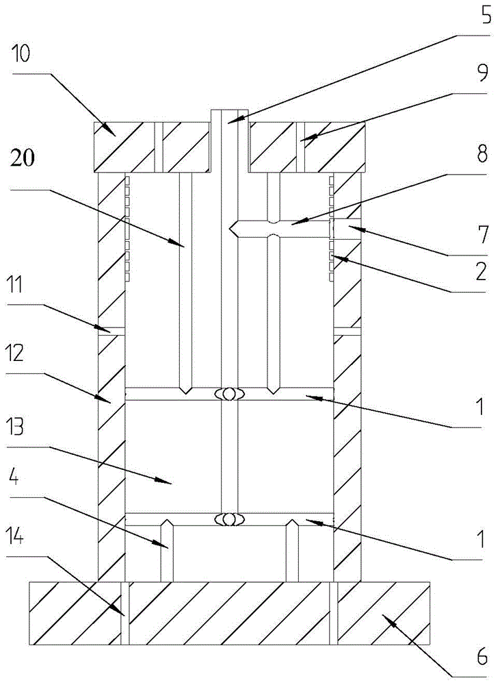
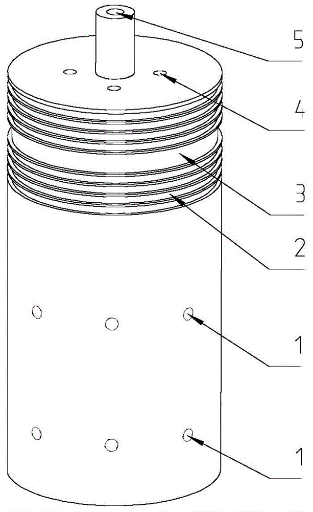
[0022] refer to Figure 1 to Figure 4 , a frictionless rotary air supply and air flotation device, comprising an inner core 13, an outer core 12 and an end cap, the inner core 13 is sleeved in the outer core 12, and the end cap includes an upper end cap 10, a lower end cap 6, the The upper and lower ends of the outer core 12 are fixed with the upper end cover 10 and the lower end cover 6 by bolts, and there are small gaps between the inner core 13 and the outer core 12 and between the inner core 13 and the upper end cover 10 and the lower end cover 6;

[0023] The upper end of the inner core 13 is provided with an annular air cavity groove 3, four annular sealing grooves 2 are opened on both sides of the annular air cavity groove 3, and the annular air cavity groove 3 is perforated in the radial direction. An air intake hole 8 is formed toward the center of the circle...


PUM


Abstract

The invention relates to a friction-free rotary air supply air flotation device, which is characterized in that four annular sealing grooves are respectively formed in each of the two sides of an annular air cavity groove at the upper end of an inner core; through holes are formed along the radial direction and introduced to the circle center to form air intake holes; radial throttling orifices are uniformly distributed on the circumference at the middle part and the area close to the bottom of the inner core, and the radial throttling orifices are communicated at the circle center along the radial direction; a blind hole at the top end is formed at the circle center of the top end of the inner core along the axial direction to form an air outlet, and the air outlet is communicated with the radial throttling orifices and the air intake holes; blind holes are formed at the bottom end of the inner core along the axial direction to form bottom end axial throttling orifices, and the bottom end axial throttling orifices are uniformly distributed at the bottom end of the inner core and communicated with the bottom radial throttling orifices; blind holes are formed at the top end of the inner core along the axial direction to form top end axial throttling orifices, and the top end axial throttling orifices are uniformly distributed at the top end of the inner core and communicated with the middle part radial throttling orifices and the air intake holes; a threaded air inlet is formed at the upper part of an outer core; and pressure relief holes are uniformly distributed at the middle part of the outer core and are communicated with pressure relief grooves on the inner wall of the outer core. The friction-free rotary air supply air flotation device has the beneficial effects that air supply can be carried out continuously and is not affected by air pipe disturbance.

Description

technical field [0001] The present invention relates to the field of air flotation. Background technique [0002] The air suspension system can not only be used in the field of axial movement of the air suspension shaft, but also in the field of rotation of the air suspension shaft. It uses gas instead of oil as a lubricant to form an air film between the shaft and the bearing sleeve, so that the Ideal support element where the moving and stationary surfaces avoid direct contact. [0003] In the application of a thrust air bearing, the thrust bearing moves with the bearing member in the plane without friction, such as realizing the frictionless unfolding movement of the vertically placed multi-folding hinge in the plane, and the bottom of the hinge plate can move without friction in the plane. The thrust air bearing provides frictionless support and realizes frictionless rotation between the hinges. At the same time, the thrust air bearing moves without friction in the plan...

Claims


Application Information

Patent Timeline
Patent Type & Authority Patents(China)
IPC IPC(8): F16C32/06
Inventor 孙建辉单晓杭周海清
Owner 铜陵汇恒电子科技有限公司
Why Eureka
Try Eureka