Rotary air supply device capable of supplying air in series

A rotary gas supply and gas storage technology, applied in the directions of bearings, shafts and bearings, mechanical equipment, etc., can solve problems such as tracheal bending disturbance and achieve the effect of continuous gas supply

Active Publication Date: 2015-02-18
铜陵汇恒电子科技有限公司
View PDF4 Cites 0 Cited by
  • Summary
  • Abstract
  • Description
  • Claims
  • Application Information

AI Technical Summary

Problems solved by technology

[0004] In order to solve the deficiencies of the influence of the tracheal bending disturbance of the existing air flotation device, the present invention provides a frictionless rotating air supply air flotation device that can continuously supply air and is not affected by the tracheal disturbance

Method used


Image

  • Rotary air supply device capable of supplying air in series
  • Rotary air supply device capable of supplying air in series
  • Rotary air supply device capable of supplying air in series

Examples


Embodiment Construction

[0021] The present invention will be further described below in conjunction with the accompanying drawings.

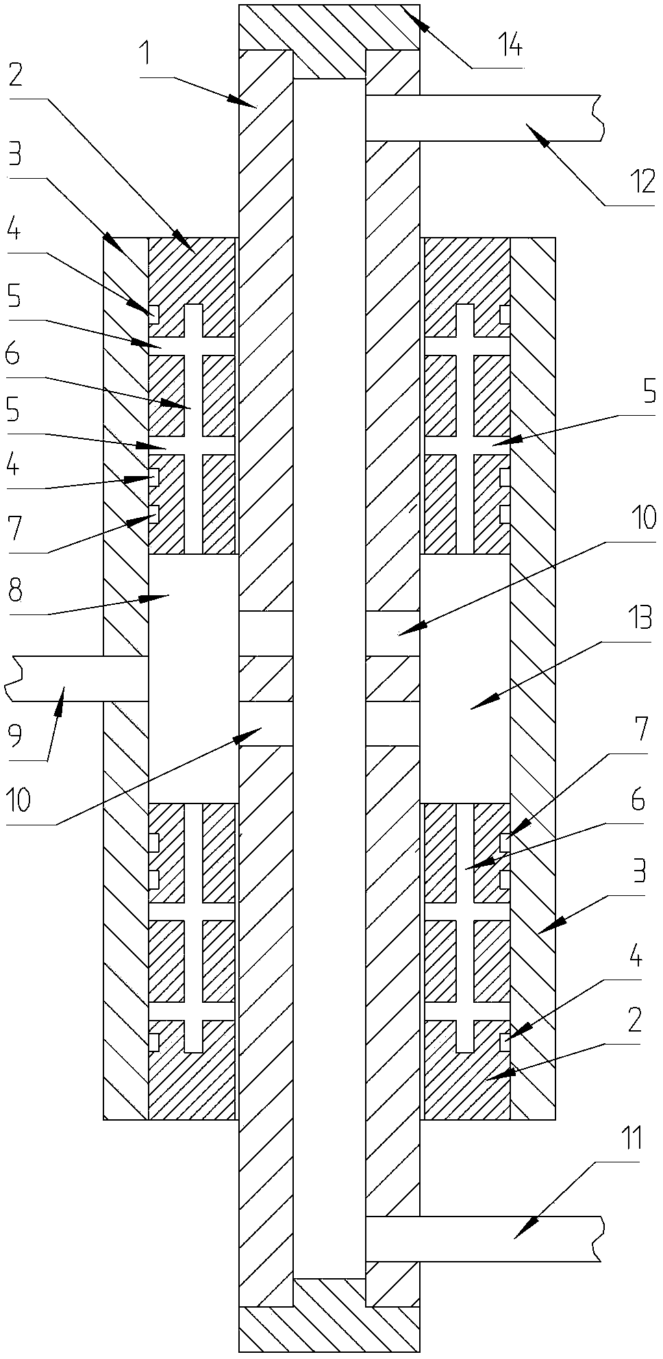
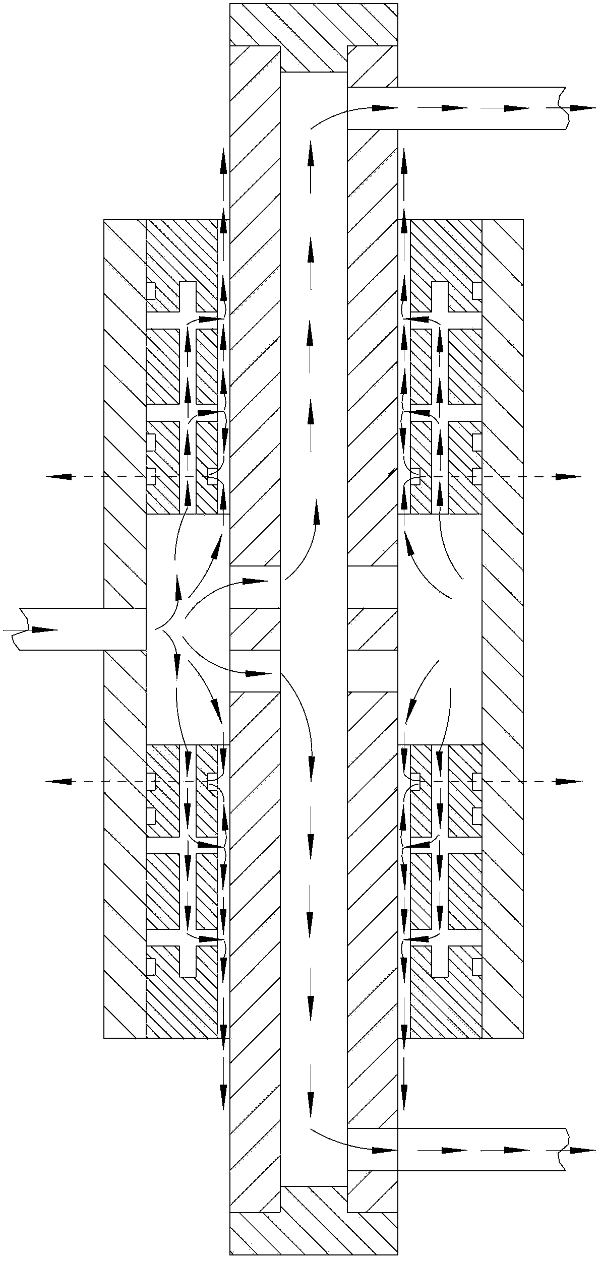
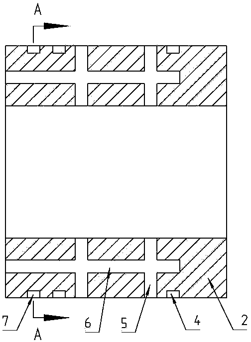
[0022] refer to Figure 1~Figure 7 , a rotary air supply device that can realize air supply in series, including an air flotation shaft 1, a pair of air flotation sleeves 2 and an air storage sleeve 3, the air flotation shaft 1 is set in the air flotation sleeve 2, and the air flotation There are two sleeves 2, and the periphery of the air-floating sleeve 2 is fixed with the air storage sleeve 3, and a high-pressure chamber 13 is formed between the air storage sleeve 3, the two air-floating sleeves 2, and the air-floating shaft 1, and the air storage sleeve 3 There is an air inlet 9 on it and communicates with the high-pressure chamber 13. There is an axial through hole in the center of the air-floating shaft 1. Both ends of the air-floating shaft 1 are sealed by end caps 14. Air outlets 11 and 12, the air bearing shaft 1 is located in the high-pressure chamber, an...


PUM


Abstract

A rotary air supply device capable of supplying air in series includes an air supporting shaft, a pair of air supporting sleeves, and an air storage sleeve, wherein the air supporting shaft is mounted in the air supporting sleeves in a sleeving method; the number of the air supporting sleeves is two; the peripheries of the air supporting sleeves are fixed together with the air storage sleeve; a high pressure cavity is formed among the air storage sleeve, the two air supporting sleeves and the air supporting shaft; the air storage sleeve is provided with an air inlet and is communicated with the high pressure cavity; an axial through hole is formed in the center of the air supporting shaft; two ends of the air supporting shaft are sealed through end covers; air outlets are arranged at the upper end and the lower end of the air supporting shaft; multiple radial through holes are uniformly distributed at a part, located in the high pressure cavity, of the air supporting shaft; flow restriction orifices are uniformly distributed on the air supporting sleeves in the peripheral direction; blind holes are formed in each air supporting sleeve in the axial direction from the end surface on the high pressure cavity side to form air inlet holes communicated with the flow restriction orifices; two ends of each air supporting sleeve are hermetically connected with the air storage sleeve; air discharge holes are uniformly distributed on the peripheries, on the side close to the high pressure cavity, of the air supporting sleeves; the air discharge holes and the air inlet holes form an included angle and are separated from each other; air discharge slots are formed on peripheral surfaces where the air discharge holes are located; and through holes formed in the air storage sleeve are communicated with the air discharge slots. The rotary air supply device can supply air continuously and is free from disturbance of air pipes.

Description

technical field [0001] The invention relates to the field of air flotation. Background technique [0002] With the development of science and technology, gas lubrication is often used instead of ordinary mechanical lubrication, and high-pressure gas is introduced into the gap between objects in relative motion to form a gas film, avoiding direct contact to achieve frictionless motion. [0003] Air flotation devices have different ways of forming gas films and different gas supply methods. Usually, the gas pipe is used to introduce gas into the high-pressure chamber, but no matter which gas supply method is used, the air pipe must not disturb the air flotation device. For some Compared with the air flotation device with air source movement, there is a big problem in air flotation gas supply. For example, the side of the vertically placed folding hinges connected by hinges, the bottom uses multiple air bearing pads to realize the frictionless unfolding movement in the plane, ...

Claims


Application Information

Patent Timeline
Patent Type & Authority Patents(China)
IPC IPC(8): F16C32/06
Inventor 单晓杭周海清孙建辉
Owner 铜陵汇恒电子科技有限公司
Why Eureka
Try Eureka