Electronic pilot burner

An ever-bright lamp and electronic technology, applied in lighting and heating equipment, combustion ignition, combustion methods, etc., can solve problems such as damage to supporting equipment, consumption of combustible gas, and large space occupation, and achieve convenient maintenance, saving equipment investment, and saving resources. Effect

Inactive Publication Date: 2013-04-24
辽宁省电子研究设计院有限公司
View PDF6 Cites 8 Cited by
  • Summary
  • Abstract
  • Description
  • Claims
  • Application Information

AI Technical Summary

Problems solved by technology

The existing technical problems are: First, the traditional permanent lamp needs a large amount of combustible gas as the raw material for flame combustion during the combustion process, thus consuming a large amount of combustible gas and wasting energy, and it also needs to be equipped with corresponding gas supply equipment and pipeline systems , so the investment is large and takes up a large space; secondly, because the traditional lamp is ignited by combustible gas, it belongs to gas combustion, and its flame cannot resist extreme bad weather, especially the environment where the offshore drilling platform is located. Flame-off is prone to occur during violent storms. Therefore, the traditional permanent lamp cannot guarantee reliable permanent burning under all-weather conditions of wind, frost, snow and rain throughout the year, and the supporting equipment of the traditional permanent lamp also has a certain probability of damage, so there is a relatively high It is a big safety hazard, and at the same time, it also causes certain pollution to the environment during the combustion process.

Method used


Image

  • Electronic pilot burner
  • Electronic pilot burner
  • Electronic pilot burner

Examples


Embodiment Construction

[0046] The present invention will be described in detail below in conjunction with the accompanying drawings.

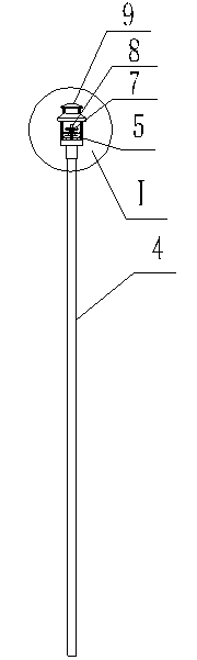
[0047]As shown in the accompanying drawings, the present invention has a metal conductive rod 1 used to be connected with a high voltage device. The length of the metal conductive rod 1 is 1800 mm to 2700 mm, and the top of the metal conductive rod 1 is processed with external threads. In order to ensure reliable The high-voltage electricity is sent to the discharge ignition head, and the metal conductive rod 1 is covered with a quartz protection tube 2, and the quartz protection tube 2 is composed of at least 3 stepped quartz tubes 2-1 connected to each other. Tube 2-1 The inner diameter of the thin tube section is 6-8mm, and the inner diameter of the thick tube section is 14-18mm. The length is adjusted with the voltage level to ensure the minimum discharge distance and meet the needs of relatively slender metal conductive rods, and enhance its performance in tr...


PUM


Abstract

An electronic pilot burner solves the problems of energy waste, environmental pollution and low reliability of existing pilot burner, and is characterized by comprising a metal conducting rod connected with a high-voltage device, a discharge igniting head is mounted at the top end of the metal conducting rod, a quartz protection tube is sleeved outside the metal conducting tube, a metal protection tube is mounted outside the quartz protection tube, a burner holder is mounted at the top end of the metal protection tube, high-temperature-resisting mineral sand is filled between the metal protection tube and the quartz protection tube, a tower-shaped high-voltage quartz insulator is mounted on the burner holder, burner housing support columns are arranged on a current conducting platform of the burner holder, and outer edges of the burner housing support columns are connected with a burner housing through a connecting ring. The electronic pilot burner has the advantages that electric energy can be adopted to substitute for traditional inflammable gas to form pilot burner flame, blow-off can be avoided, and corresponding gas supply equipment and pipeline systems are not need to be provided, so that investment is reduced, space is saved, reliable eternal burning is kept in all weathers, and further energy saving, environmental protection, safety and equipment investment saving are achieved.

Description

technical field [0001] The invention belongs to the technical field of electronic control, and particularly relates to an electronic ever-burning lamp used for igniting combustible gases that cannot be recovered in the production process of petrochemical, ocean drilling platforms and iron and steel smelting enterprises. Background technique [0002] In the production process of petroleum and petrochemical, offshore oil and steel smelting enterprises, there are a large amount of combustible gases that cannot be recovered. The discharge of these combustible gases into the atmosphere will not only cause great harm to production safety, but also cause serious pollution to the environment. Preventing these combustible gases from being discharged into the atmosphere will cause great harm to production safety and serious pollution to the environment. These combustible gases need to be reliably burned by the flare system. In the prior art, the flare system adopts a secondary ignitio...

Claims


Application Information

Patent Timeline
Patent Type & Authority Applications(China)
IPC IPC(8): F23Q7/00
Inventor 詹世涛任志刚李贵军艾江山魏强李晓云何海洲
Owner 辽宁省电子研究设计院有限公司
Why Eureka
Try Eureka