Composite drill bit with cutter blade provided with cutter disk cutting structure

A technology of cutting structure and compound drill bit, which is applied in the direction of drill bit, drilling equipment, earthwork drilling, etc., can solve the problems of increasing the working load of PDC teeth, large space of drill bit, and accelerated wear speed, so as to improve the performance and life of the drill bit and save the drill bit The effect of shrinking space and volume

Active Publication Date: 2013-05-08
CHENGDU WEIYI PETROLEUM TECH
View PDF8 Cites 12 Cited by
  • Summary
  • Abstract
  • Description
  • Claims
  • Application Information

AI Technical Summary

Problems solved by technology

This fixed-tooth PDC drill has four main disadvantages:
[0007]Second, the failure of individual teeth on the bit (tooth loss, fracture or excessive wear, etc.) can significantly increase the work of the PDC teeth near the bottom hole annulus of the failed tooth The load accelerates its wear rate, which leads to premature failure of the drill bit
[0009] Fourth, increasing the number of cutting teeth on the drill bit can reduce the working load of the cutting teeth, thus effectively reducing the wear rate of the cutting teeth and improving the working life of the drill bit. But it will also reduce the drilling efficiency of the drill bit
However, in further research, it was found that this drill bit structure has the following disadvantages: although the rotating wheel with cutting teeth and the fixed cutting structure with fixed cutting teeth can exert their effects independently, the rotating wheel and its supporting structure must be It is an independent cutting structure unit on the drill body, so it occupies a relatively large space on the drill bit. Under the condition of extremely limited tooth arrangement space, the waste of space means the sacrifice of drill performance to a large extent. The design of the cutting structure of the drill bit is very unfavorable
The existence of the above-mentioned defects has hindered the practical application of this scheme with excellent technical effect

Method used


Image

  • Composite drill bit with cutter blade provided with cutter disk cutting structure
  • Composite drill bit with cutter blade provided with cutter disk cutting structure
  • Composite drill bit with cutter blade provided with cutter disk cutting structure

Examples


Embodiment 1

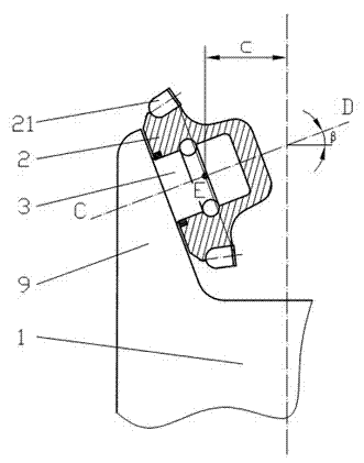
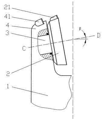
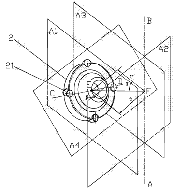
[0086] Such as image 3 , 4 , shown in 5, 6, and 7: a compound drill bit with a disc cutter cutting structure on the blade, including a drill body 1, a fixed blade 4, and a disc cutter 2, the drill body 1 is provided with a fixed blade 4, and the fixed blade Fixed cutting teeth 41 are arranged on the wing 4, the range of the offset angle α of the disc cutter 2 is 20°≤|α|≤90°, and at least one disc cutter 2 and the disc cutter cutting tooth 21 on the drill body 1 And the disk cutter cutting unit constituted by the disk cutter shaft 3, at least one disk cutter cutting unit is arranged on the fixed blade 4, and the disk cutter 2 and the fixed blade 4 form a rotational connection. The fixed blade 4 is provided with disc cutter grooves, and the disc cutter cutting unit is arranged in the disc cutter groove. Both ends or one end of the disc cutter shaft 3 are connected to the fixed blade 4, and the disc cutter 2 is connected to the fixed blade through the disc cutter shaft 3. 4 to ...

Embodiment 2

[0088] This embodiment is basically the same as Embodiment 1, the difference being that: the drill bit body 1 is also provided with an independent fixed cutting structure consisting of an independent fixed blade 4 and its fixed cutting teeth 41 . Such as Figure 12 , 20 As shown, two rows of fixed cutting teeth 41 are arranged on the fixed blade 4 provided with the disc cutter cutting unit. On the basis of the disc cutter cutting unit, the drill body 1 is also provided with a fixed cutting structure independent of the disc cutter cutting unit. 4. The added fixed cutting structure 4 has increased the arrangement of teeth of the drill bit, making the drill bit more suitable for drilling in harder formations.

Embodiment 3

[0090] This embodiment is basically the same as Embodiment 1 or 2, the difference being that there are both positive and negative offset disk cutter cutting units on the drill body 1 . Such as Figure 14 , 15, 16, and 17, the distance between the positive and negative offset disc cutter cutting units is relatively close, and the shaft end of the disc cutter shaft 3 that is closer to the disc cutter 2 can be connected to the same fixed blade 4, so that the drill bit structure is more Compact, when the outer diameter of the drill bit is constant, more disc cutter cutting units and the number of cutting teeth can be set; at the same time, the fixed blades 4 between the disc cutter cutting units and the fixed blades 4 at both ends of the disc cutter cutting unit are Fixed cutting teeth 41 may be provided to form a fixed cutting structure. It can be seen from the figure that this embodiment has a compact structure and a large space for the fixed cutting teeth to arrange the teeth...


PUM


Abstract

The invention discloses a composite drill bit with a cutter blade provided with a cutter disk cutting structure, and belongs to the technical field of drilling equipment in petroleum and gas, mine engineering, building foundation engineering construction, geology, hydrology and the like. The composite drill bit with the cutter blade provided with the cutter disk cutting structure comprises a drill bit body, a fixed cutter blade and cutter disks. The drill bit body is provided with the fixed cutter blade, the fixed cutter blade is provided with fixed cutting teeth, and a range of a deflection angle alpha is 20 degrees <=|alpha|<= 90 degrees. The drill bit body is provided with at least one cutter disk cutting unit which is composed of the cutter disk, the cutter disk cutting teeth arranged on the cutter disk and a cutter disk shaft. The at least one cutter cutting unit is arranged on the fixed cutter blade. The cutter disk is connected with the fixed cutter blade in a rotating mode. Structural features of the cutter blade type drill bit are utilized sufficiently, and thus a geometry space of a drill bit cutting structure area is saved, combination property of the drill bit is improved.

Description

technical field [0001] The invention belongs to the technical field of drilling equipment such as petroleum and natural gas, mining engineering, building foundation engineering construction, geology, hydrology, etc., and specifically relates to a drill bit. Background technique [0002] The drill bit is a rock-breaking tool used in drilling engineering to break rock and form a wellbore. Tri-cone bits and PDC (polycrystalline diamond compact) bits are the most widely used bits in drilling engineering today. [0003] Tri-cone bits mainly break rock in the form of impact crushing. Most of the cone offset angles of the existing tricone bits do not exceed 5°. When the drill bit rotates and drills at the bottom of the well, the wheel body speed ratio (the ratio of the cone speed to the drill bit speed when the drill bit rotates and drills) is greater than 1. The rotation speed of the wheel around the journal of the tooth palm is fast, the contact time between the teeth on the to...

Claims


Application Information

Patent Timeline
Patent Type & Authority Applications(China)
IPC IPC(8): E21B10/43
CPCE21B10/43E21B10/12E21B10/10E21B10/46E21B10/52E21B10/55E21B10/14E21B10/50E21B10/54
Inventor 杨立源
Owner CHENGDU WEIYI PETROLEUM TECH
Why Eureka
Try Eureka