Unlock instant, AI-driven research and patent intelligence for your innovation.

Method and device for wireless video surveillance

A wireless video monitoring and video monitoring technology, applied in the field of communication, can solve the problems of increased image packet loss rate, easy image mosaic, unable to guarantee the quality of monitoring video stream, etc., and achieve the effect of improving stability

Active Publication Date: 2016-12-14
CHINA MOBILE COMM GRP CO LTD
View PDF6 Cites 0 Cited by
  • Summary
  • Abstract
  • Description
  • Claims
  • Application Information

AI Technical Summary

Problems solved by technology

[0008] Existing solutions reduce the frame rate of video frames when the effective transmission bandwidth of the video stream is reduced or the bit error rate is increased, but still use the combination of I frame and P frame for video frame compression, resulting in the reduction of video quality
This is because the frame rate of the video frame decreases, and the correlation of adjacent frames will also decrease accordingly. The compression efficiency of the P frame decreases, and the compressed code stream of the P frame increases. With the increase of the compressed code stream of the P frame, only further Reduce the video frame rate until it meets the requirements of the current effective transmission bandwidth. At the same time, the increase in the bit error rate will also lead to an increase in the image packet loss rate. The image is prone to mosaic and image error accumulation, which eventually leads to the reduction of video quality.
[0009] In the existing solution, when the communication between the monitoring front end and the monitoring center is interrupted, the monitoring front end continues to transmit the video stream after the communication with the monitoring center is resumed, but what it continues to transmit is the video stream collected after the communication with the monitoring center is resumed. Therefore, the monitoring center cannot obtain the video stream during the period of communication interruption
[0010] It can be seen that the existing wireless video surveillance solutions, in some special cases, cannot guarantee the quality of the surveillance video stream, or even fail to provide the surveillance video stream, thus resulting in poor stability of the wireless video surveillance

Method used


Image

  • Method and device for wireless video surveillance
  • Method and device for wireless video surveillance
  • Method and device for wireless video surveillance

Examples


Embodiment Construction

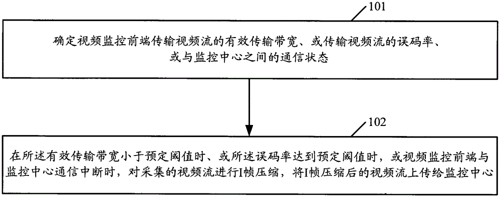
[0024] figure 1 It is a flow chart of the wireless video surveillance method provided by the present invention.

[0025] like figure 1 As shown, the process includes:

[0026] Step 101, determine the effective transmission bandwidth of the video surveillance front-end to transmit the video stream, or the bit error rate of the transmitted video stream, or the communication status with the monitoring center.

[0027] Step 102, when the effective transmission bandwidth is less than a predetermined threshold, or when the bit error rate reaches a predetermined threshold, or when the communication between the video monitoring front end and the monitoring center is interrupted, perform I frame compression on the collected video stream, and compress the I frame The final video stream is uploaded to the monitoring center.

[0028] When the wireless video surveillance front-end is in a mobile application scenario, the effective transmission bandwidth of the video stream will be great...


PUM


Abstract

The embodiment of the invention discloses a wireless video monitoring method and equipment. The method includes: determining the effective transmission bandwidth of the video monitoring front end for transmitting video streams, or the bit error rate of the transmitted video stream, or the communication status with the monitoring center, when the effective transmission bandwidth is less than a predetermined threshold, or the error rate When the code rate reaches a predetermined threshold, or when the communication between the video monitoring front end and the monitoring center is interrupted, I-frame compression is performed on the collected video stream, and the I-frame-compressed video stream is uploaded to the monitoring center. The application of the invention can improve the stability of wireless video monitoring.

Description

technical field [0001] The present invention relates to the technical field of communication, in particular to a wireless video monitoring method, system and equipment. Background technique [0002] At present, wireless video surveillance has a wide range of applications, for example, wireless video surveillance in scenarios where wired networks cannot be reached or wired networks are too expensive. [0003] The monitoring front end of the wireless video surveillance loads video stream collection and uploads the collected video stream to the monitoring center. Wherein, the monitoring front end needs to compress the video stream before uploading the video stream to the monitoring center. At present, the monitoring front end of wireless video surveillance adopts a combination of intra-frame compression (I frame) and inter-frame compression (P frame method) to compress the collected video stream, and then upload the compressed video stream to the monitoring center. . [0004...

Claims


Application Information

Patent Timeline
Patent Type & Authority Patents(China)
IPC IPC(8): H04N7/18
Inventor 柴鑫刚郑冬冬
Owner CHINA MOBILE COMM GRP CO LTD