A side-suction and upper-discharge range hood

A range hood and oil fume technology, which is applied in the direction of oil fume removal, heating methods, household heating, etc., can solve the problems of low smoking efficiency of volute components, low efficiency of oil fume suction and exhaust, poor grease filtering effect, etc., to improve the work effect and service life, good filtering effect, and high oil fume inhalation rate

Active Publication Date: 2015-12-23
ZHEJIANG SANFER ELECTRIC
View PDF9 Cites 0 Cited by
  • Summary
  • Abstract
  • Description
  • Claims
  • Application Information

AI Technical Summary

Problems solved by technology

[0002]The range hood has become an indispensable appliance in the kitchen. The smoke inlet chamber of the traditional range hood is mostly open, and some are close suction, but the range hood The grease filtering effect in the volute is poor, the volute is inside or above the inside of the shell, the smoke collection technology of the shell causes serious grease accumulation in the shell and the volute assembly, due to the placement of the volute, it is difficult to clean the surrounding area, and the volute assembly The smoking efficiency is low, and the fan assembly is generally installed in the smoke collection cavity, and the surroundings of the fan assembly are covered by oil fumes, and the oil fume runs around the fan assembly. Touch the user's face and other positions, which will affect the user's health

Method used


Image

  • A side-suction and upper-discharge range hood
  • A side-suction and upper-discharge range hood
  • A side-suction and upper-discharge range hood

Examples


Embodiment Construction

[0022] The present invention will be further described below with reference to the accompanying drawings.

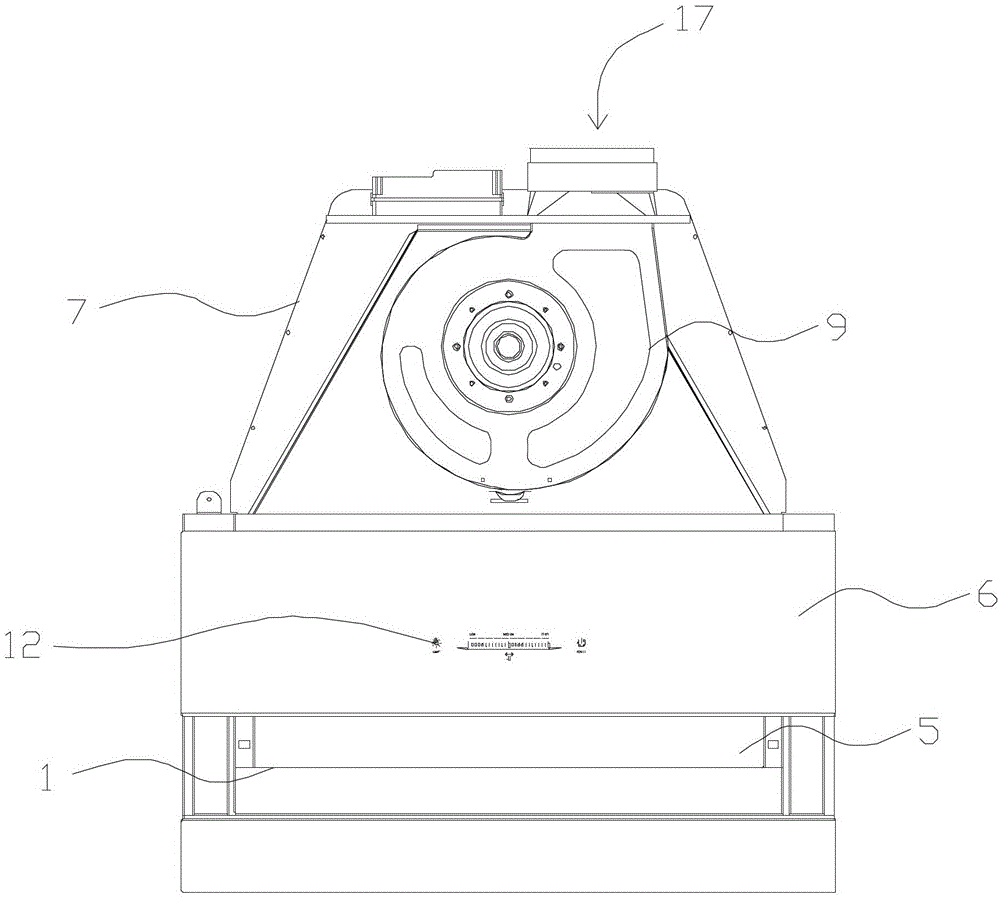
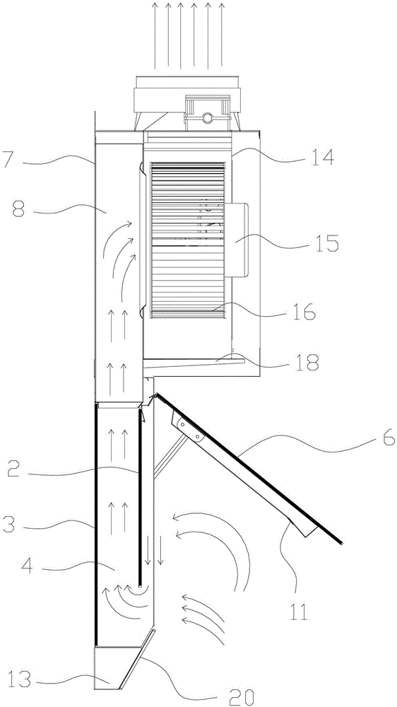
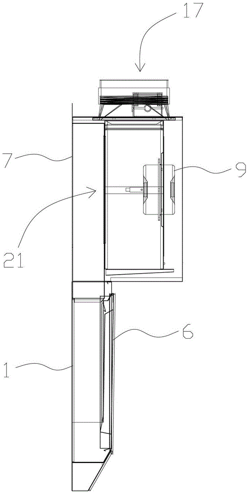
[0023] Such as Figure 1-Figure 4 As shown, a side-suction and upper-discharge range hood described in this embodiment includes a flat straight smoke inlet box 1 and a fan assembly 9. The smoke inlet box 1 includes a front panel 2 and a rear panel 3 and the smoke inlet There is a vertical smoke inlet chamber 4 inside the box 1. The smoke inlet chamber 4 is located between the front board 2 and the rear board 3 and opens upward. The lower end of the front board 2 has a smoke inlet chamber connected to the smoke chamber. 5, the outer side of the front plate 2 is provided with a rotating panel 6 that can open or close the smoke inlet 5, and a smoke collection box 7 is provided above the smoke inlet box 1, and the inside of the smoke collection box 7 is There is a smoke collecting chamber 8 connected with the upper mouth of the smoke inlet chamber, and the fan assembly 9 is...


PUM


Abstract

The invention provides a side-suction upward-discharge type range hood, and relates to the technical field of range hoods. A volute of a traditional range hood is positioned on the interior of a shell or the upward side of the interior of the shell, and greases are seriously accumulated on the shell and a volute component, thus cleaning is troublesome, the greases in the lampblack are difficult to filter, and the lampblack suction effect is poor. The range hood provided by the invention comprises a smoke inlet box and a blower component, and is characterized in that the smoke inlet box comprises a front plate and a rear plate, and a vertical smoke inlet chamber is formed in the smoke inlet box; the smoke inlet chamber is located between the front plate and the rear plate and opened upwards, a smoke inlet communicated with the smoke inlet chamber is formed on the lower end of the front plate, the outer side of the front plate is provided with a rotation panel which can open or close the smoke inlet, a smoke collection box is arranged above the smoke inlet box, a smoke collection chamber communicated with the upper port of the smoke inlet chamber is formed in the smoke collection box, the blower component is vertically arranged on the one side of the smoke collection chamber, and comprises an air inlet and an air outlet, and the air inlet is communicated with the smoke collection chamber. The range hood provided by the technical scheme has a good effect on filtrating greases, thus generating less influence on the blower component; and the discharge is environmentally-friendly, the efficiency of lampblack discharge is high, and the volume is small.

Description

technical field [0001] The invention relates to the technical field of range hoods, in particular to a side-suction and top-discharging range hood. Background technique [0002] The range hood has become an indispensable appliance in the kitchen. The smoke inlet chamber of the traditional range hood is mostly open, and some are near-suction, but the oil filtering effect in the range hood is poor. Above the interior, the smoke collection technology of the casing causes serious grease accumulation on the casing and the volute assembly. Due to the placement of the volute, it is difficult to clean the surrounding area, and the smoking efficiency of the volute assembly is low, and the fan assembly is generally installed in the smoke collection chamber. , The surroundings of the fan assembly are covered by oil fume, and the oil fume scurry around the fan assembly, and the efficiency of oil fume suction and exhaust is low. Contents of the invention [0003] The object of the pre...

Claims


Application Information

Patent Timeline
Patent Type & Authority Patents(China)
IPC IPC(8): F24C15/20
Inventor 邵贤庆茹永龙
Owner ZHEJIANG SANFER ELECTRIC
Why Eureka
Try Eureka