Bilaterally rotatable end surface mechanical sealing structure with dovetail grooves

A technology of end face mechanical seal and sealing structure, which is applied in the direction of engine sealing, mechanical equipment, engine components, etc., can solve the problems of low air film stiffness, weak dynamic pressure effect, poor anti-disturbance performance, etc., and achieve air film stiffness Large, improve the air film stiffness, prolong the effect of service life

Active Publication Date: 2013-06-05
ZHEJIANG UNIV OF TECH
View PDF13 Cites 14 Cited by
  • Summary
  • Abstract
  • Description
  • Claims
  • Application Information

AI Technical Summary

Problems solved by technology

[0003] In order to overcome the deficiencies such as low air film rigidity at high speed, weak dynamic pressure effect, small opening force of the end face or poor anti-disturbance performance of the existing dry gas seal with two-way rotating spiral groove, the present invention provides a dry gas seal that operates at high speed. Under working conditions, the mechanical seal structure of the dovetail groove end face with good hydrodynamic pressure effect and high air film rigidity can rotate in both directions

Method used


Image

  • Bilaterally rotatable end surface mechanical sealing structure with dovetail grooves
  • Bilaterally rotatable end surface mechanical sealing structure with dovetail grooves
  • Bilaterally rotatable end surface mechanical sealing structure with dovetail grooves

Examples


Embodiment 1

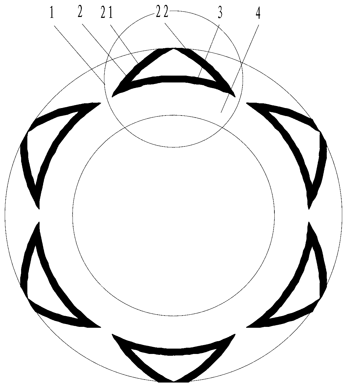
[0026] refer to figure 1 , a bidirectionally rotatable dovetail groove end face mechanical seal structure, including a moving ring, a static ring, etc. Two-way rotating dovetail grooves, each dovetail groove is composed of a pair of reversely arranged spiral grooves 21 and 22 and an arc groove 3 connecting the roots of the two spiral grooves, forming a shape similar to a dovetail, in which the spiral groove 2 is located at the high pressure The side is upstream, and the arc groove 3 is located on the low pressure side, namely downstream; the direction of the helix angle of the reversely arranged spiral grooves 21 and 22 is opposite, so that the mechanical seal can be applied to occasions requiring different directions of rotation; the arc groove 3 makes The sealing medium does not form a dead zone in the spiral groove 2, which strengthens the cooling and lubrication of the end face and the rapid discharge of abrasive particles.

[0027] The depth of the spiral groove 2 is h ...

Embodiment 2

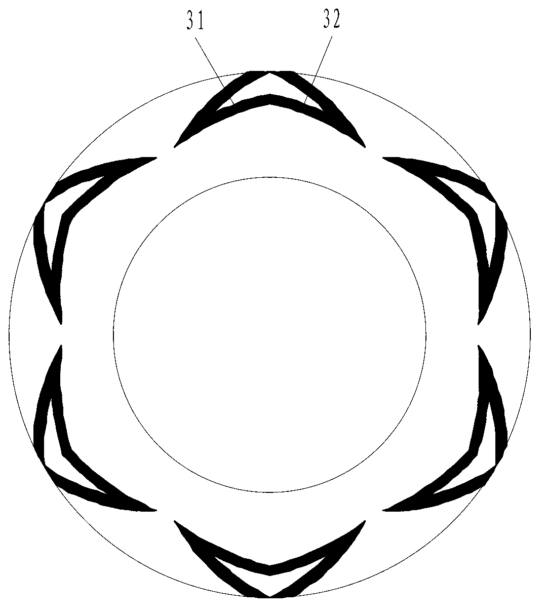
[0031] refer to figure 2 , The difference between this embodiment and Embodiment 1 is that the arc groove 3 is a pair of opposing communicating spiral grooves 31 and 32 . The rest of the structure and implementation are the same as in Embodiment 1.

Embodiment 3

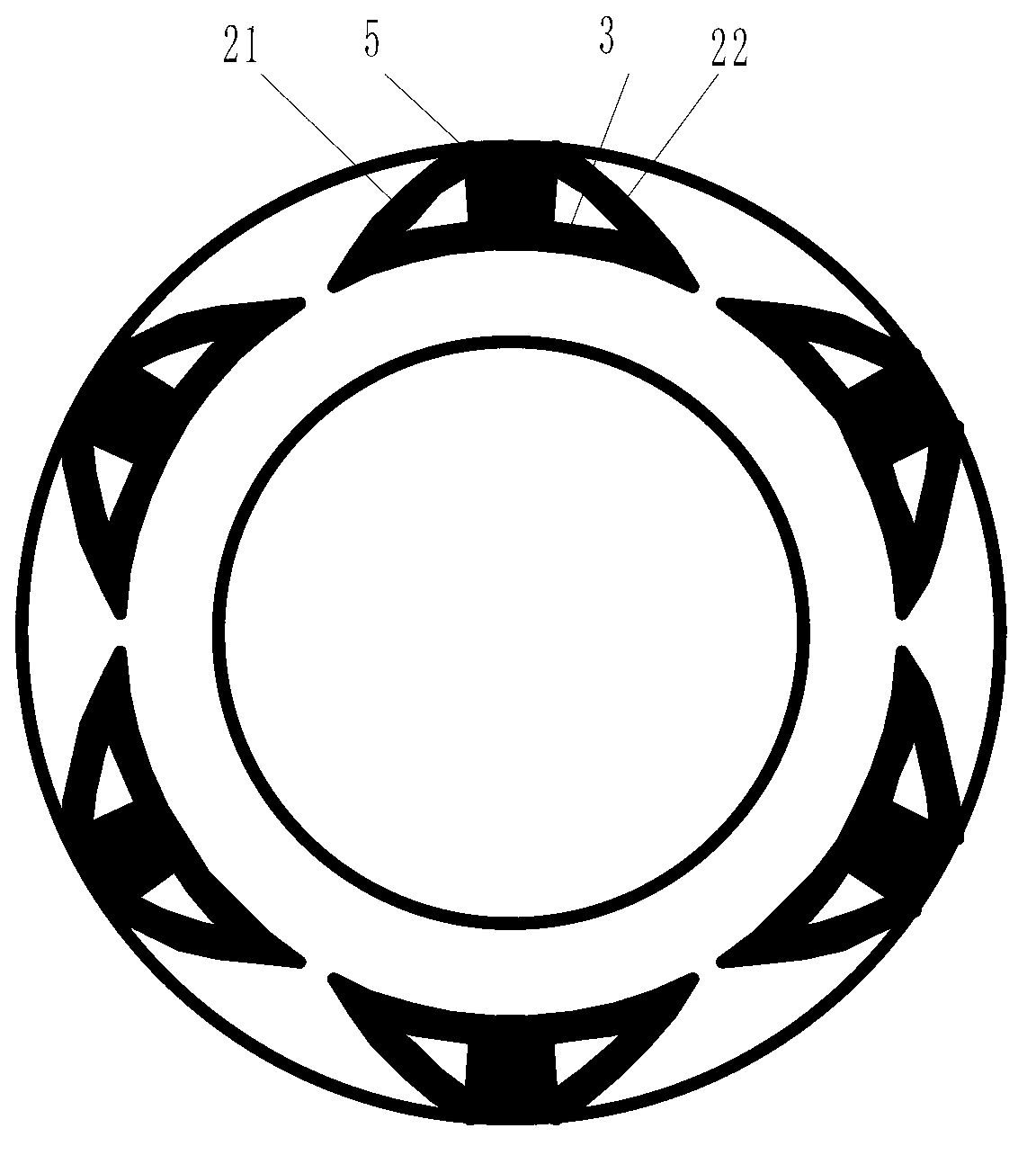
[0033] refer to image 3 The difference between this embodiment and Embodiment 1 is that there is a radial air inlet groove 5 between the spiral grooves 21 and 22, and the radial air inlet groove 5 forms a communication type with the spiral groove 2 and the arc groove 3. Dovetail groove. The rest of the structure and implementation are the same as in Embodiment 1.


PUM


Abstract

A bilaterally rotatable end surface mechanical sealing structure with dovetail grooves comprises two mechanical sealing rings including a movable ring and a fixed ring. A plurality of bilaterally rotatable dovetail grooves are arranged on end surfaces of at least one of the movable ring and the fixed ring and are circumferentially distributed along the end surfaces of the movable ring or the fixed ring, each dovetail groove comprises a pair of spiral grooves and an arc groove, the spiral grooves of each dovetail groove are reverse to each other, roots of the spiral grooves of each dovetail groove are connected with each other by the corresponding arc groove, so that each profiled groove with the shape similar to a dovetail is formed, each spiral groove is positioned on a high-pressure side, namely the upstream, each arc groove is positioned on a low-pressure side, namely the downstream, and directions of spiral angles of the spiral grooves which are reverse to one another correspondingly are opposite to one another.

Description

technical field [0001] The invention relates to a gas end face mechanical seal structure of a rotary fluid machine, in particular to a bidirectionally rotatable gas seal end face structure, which is used for shaft end seals of various compressors, expanders, pumps, reaction kettles and other rotating machines . Background technique [0002] Bidirectionally rotatable spiral groove end seals have been reported, such as Chinese patents CN1364987A, CN1206801A and CN201496542U, Chinese Science and Technology Journal "Lubrication and Sealing" No. 12, 2009, page number 60-62, foreign patents EP0499370A1, EP0632219A1, US6446976, US6575470 and US6726213, etc. have all publicly reported that the end face structure is mainly composed of several spiral grooves symmetrically arranged and non-grooved sealing dams, and some also include radial air inlet grooves. Although these helical groove dry gas seals have high fluid film stiffness, large load capacity and low friction power consumpti...

Claims


Application Information

Patent Timeline
Patent Type & Authority Applications(China)
IPC IPC(8): F16J15/40F16J15/34
Inventor 彭旭东江锦波李纪云白少先王玉明
Owner ZHEJIANG UNIV OF TECH
Why Eureka
Try Eureka