
A device for measuring aircraft pedal force and braking force and its measuring method

A technology of pedal force and brake force, which is applied in the field of devices for measuring aircraft pedal force and brake force, can solve the problems of high cost, difficult implementation, and large space occupation, and achieves convenient installation, use and adjustment, and high test accuracy , the effect of small space size

Active Publication Date: 2016-06-01
XIAN AIRCRAFT DESIGN INST OF AVIATION IND OF CHINA
View PDF5 Cites 0 Cited by
  • Summary
  • Abstract
  • Description
  • Claims
  • Application Information

AI Technical Summary

Problems solved by technology

The result of the transformation of the pedals may affect the manipulation of the pedals, and also affect the original functional characteristics of the pedals such as the strength of the pedals. very high and not universal
[0006] 2. Design special fixtures and connectors. When using general tension and pressure sensors to measure pedal force and braking force, it is necessary to assemble these scattered fixtures, connectors and tension and pressure sensors together, which takes up a lot of space. It brings great difficulties to on-site installation and use

Method used


Image

  • A device for measuring aircraft pedal force and braking force and its measuring method
  • A device for measuring aircraft pedal force and braking force and its measuring method
  • A device for measuring aircraft pedal force and braking force and its measuring method

Examples


Embodiment Construction

[0031] The present invention will be described in detail below in conjunction with the accompanying drawings and embodiments.

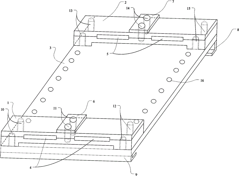
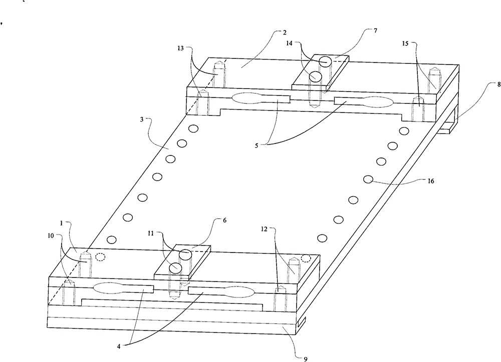
[0032] The structure of the device for measuring the pedal force and braking force of the aircraft is as follows: figure 1 As shown, the device for measuring the pedal force and braking force of an aircraft is composed of a pedal force detection unit [1], a braking force detection unit [2], a combined connection unit [3], and a fixed installation unit [8] [9]. The force detection unit [2] or the pedal force detection unit [1] are respectively arranged at the upper and lower ends of the front of the combination connection unit [3], and the upper and lower ends of the back of the combination connection unit [3] are respectively arranged at the upper and lower ends. Fixing unit [8][9] is installed at the bottom. The measuring device is installed on the pedal by installing the fixing unit [8][9], and the force is applied to the bottom of the pedal by the...


PUM


Abstract

The invention discloses a device for measuring a treading force and a braking force of an airplane and a measuring method thereof, and belongs to the field of aeronautical engineering test detecting. The device for measuring the treading force and the braking force of the airplane is characterized by comprising a treading force detecting unit, a braking force detecting unit, a combining and connecting unit and installing and fixing units, wherein the treading force detecting unit and the braking force detecting unit are respectively arranged at the upper end and the lower end of one surface of the combining and connecting unit, and an upper portion installing and fixing unit and a lower portion installing and fixing unit are respectively arranged at the upper end and lower end of the other surface of the combining and connecting unit. The measuring device is arranged on a pedal through the installing and fixing unit, applies force to the bottom of the pedal through the treading force detecting unit to drive the pedal to motion and simultaneously measure the magnitude of the applied treading force, and applies force to the top of the pedal through the braking force detecting unit to drive the pedal to motion and simultaneously measure the magnitude of the applied braking force. The device for measuring the treading force and the braking force of the airplane has the advantages of being compact and simple in structure, small in space occupation, low in costs, reliable in working, convenient to install and use and the like, and is applicable to the measurement of the treading force and braking force of all kinds of airplanes.

Description

technical field [0001] The invention belongs to the field of aeronautical engineering test and detection, and relates to a device for measuring aircraft pedal force and braking force and a measuring method thereof. Background technique [0002] The braking of the aircraft and the manipulation of the rudder are usually achieved through the operation of the pedals arranged in the cockpit of the aircraft. To operate the aircraft brakes, the pilot tilts the pedal about its bottom axis by applying force to the upper part of the pedal. The control of the rudder of the aircraft is achieved by pushing the pedal on one side forward (that is, in the direction of the front of the aircraft) to achieve the deflection of the rudder, or by pushing the pedal on the other side forward to achieve the opposite direction of the rudder deflection. [0003] After the assembly of the aircraft is completed, it is necessary to carry out necessary debugging and testing on the pedals of the aircraft...

Claims


Application Information

Patent Timeline
Patent Type & Authority Patents(China)
IPC IPC(8): G01L5/22
Inventor 支超有李霞韩小刚
Owner XIAN AIRCRAFT DESIGN INST OF AVIATION IND OF CHINA
Learn More