Base structure of injection pump

A syringe pump and base technology, applied in the field of syringe pumps, can solve the problems of inability to carry out continuous sampling, complex structure of the driving part of the syringe pump, poor reliability, etc., and achieve the effect of simple structure, reliable performance and accurate transmission

Active Publication Date: 2013-07-03
BEIJING AEONMED
View PDF5 Cites 14 Cited by
  • Summary
  • Abstract
  • Description
  • Claims
  • Application Information

AI Technical Summary

Problems solved by technology

[0005] The purpose of the present invention is to provide a syringe pump base structure with simple structure and reliable performance to solve the problem of complex structure, poor reliability and near-empty and empty alarm detection structure of the existing syringe pump driving part, which cannot carry out continuous sampling. Ensure that the syringe pump accurately completes the micro-injection work

Method used


Image

  • Base structure of injection pump
  • Base structure of injection pump
  • Base structure of injection pump

Examples


Embodiment Construction

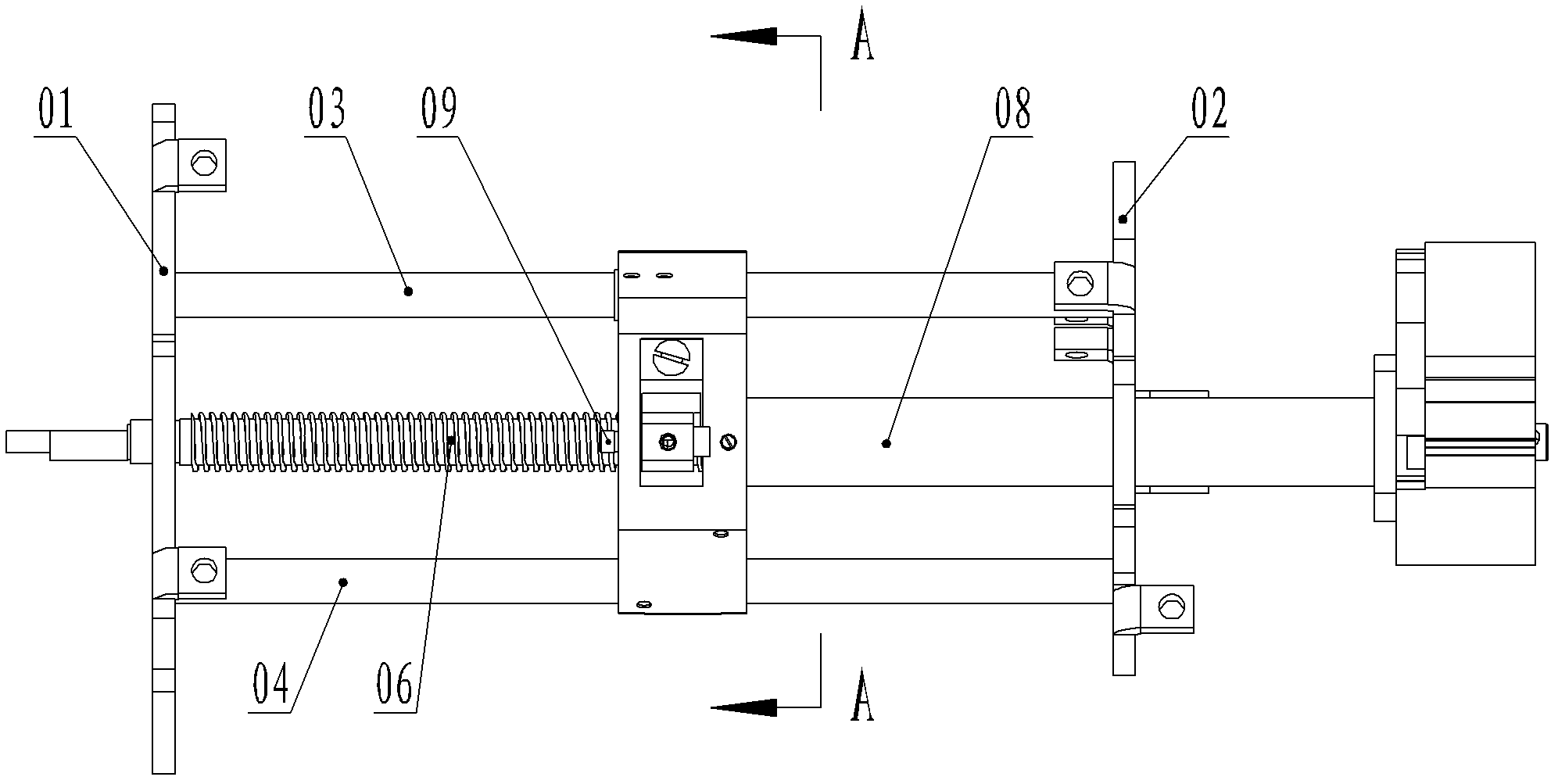
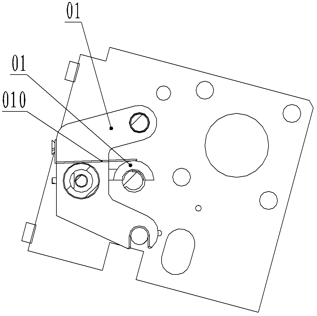
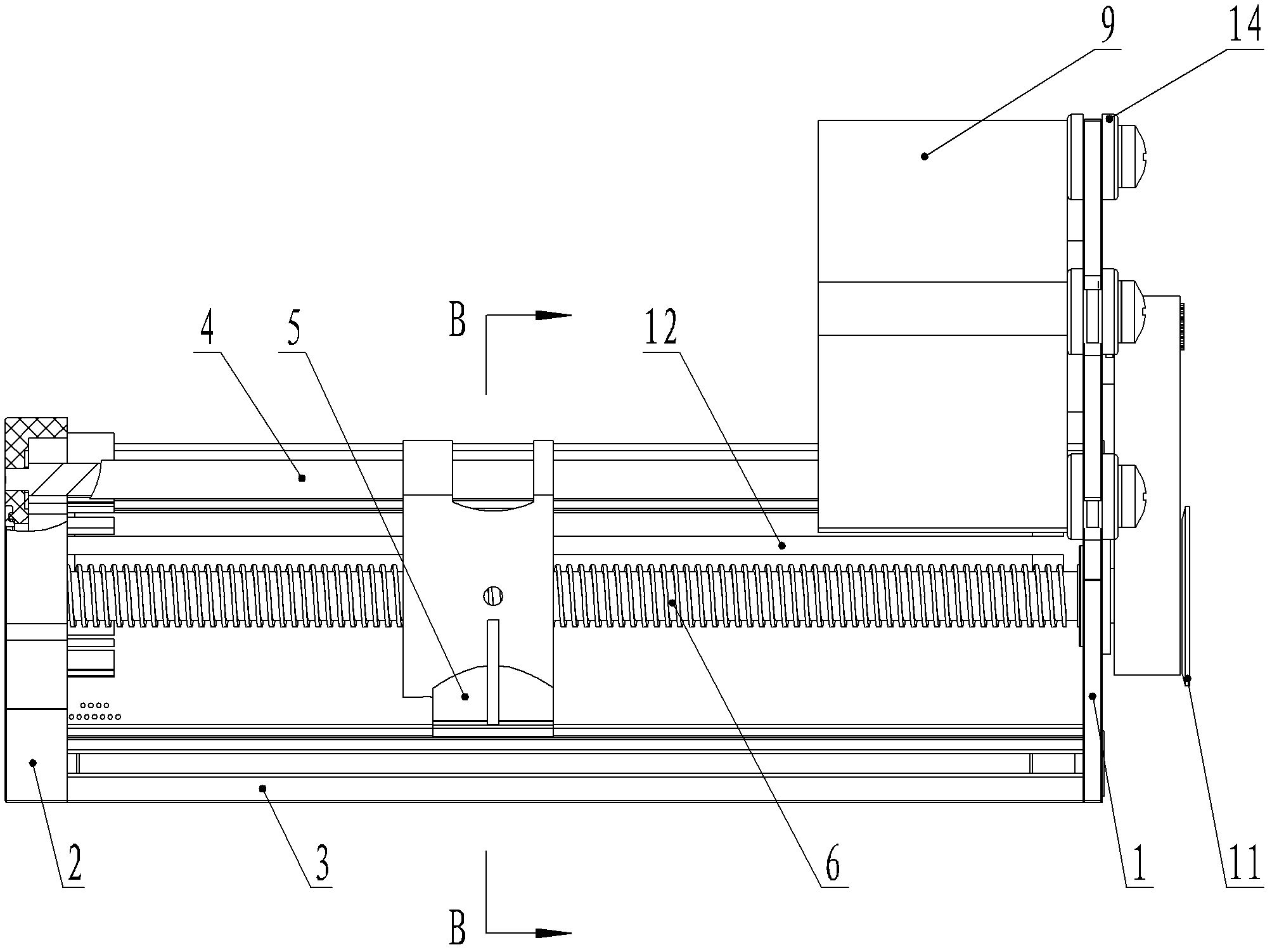
[0023] Such as Figure 3-5 As shown, the base structure of the injection pump in this embodiment includes a front mounting plate 1, a rear mounting plate 2, an aluminum profile 3, a guide rail 4, a cage 5, a lead screw 6, a spring 7, a nut 8, and a stepping motor 9 , a small synchronous pulley 10, a large synchronous pulley 11, a linear displacement sensor plate 12 and a brush 13, the front mounting plate 1 and the rear mounting plate 2 are installed on the two ends of the aluminum profile 3 respectively, and the two ends of the guide rail 4 They are arranged on the front mounting plate 1 and the rear mounting plate 2 respectively, the upper part of the cage 5 is passed through the guide rail 4 between the front mounting plate 1 and the rear mounting plate 2, and the lower part slides with the horizontal groove of the aluminum profile 3 Cooperate, the middle part is provided with a lead screw 6, the middle and lower part is provided with a screw nut mounting hole and installed...


PUM


Abstract

The invention discloses a base structure of an injection pump. According to the base structure, a step motor is utilized to drive a screw rod to rotate, a holding bracket with screw nuts is driven by the screw rod to move linearly, then a push injection head connected with the holding bracket is driven to move linearly and an injector is driven to work; the displacement of the holding bracket is continuously detected from relative sliding distance between a brush and a linear displacement sensor board coating, and the injection working and alarming of the injector are controlled in real time according to the displacement, thereby ensuring that the micro-injection of the injection pump is precisely accomplished. The base structure solves the problems that a drive part of a conventional injection pump is complicated in structure and poor in reliability, as well as the near-empty and empty alarming detection structures cannot be continuously sampled, ensures that the injection pump can accomplish the micro-injection work, and has the advantages that the structure is simple, the performance is reliable, the mounting and maintaining are convenient, and the displacement of the holding bracket and the push injection head can be continuously detected, the drive is accurate and stable.

Description

technical field [0001] The invention relates to a syringe pump, in particular to a base structure of the syringe pump. Background technique [0002] The syringe pump drives the lead screw to rotate through the motor, and the lead screw drives the injection head on the transmission nut to move linearly, thereby pushing the syringe piston to move linearly, so that the liquid in the syringe flows in one direction. The speed of injection depends on the speed of the drive nut. speed of movement. After the movement speed is calculated by the microprocessor, the driving pulse is sent out to control the operation of the stepping motor. [0003] At present, because the syringe pump can accurately complete micro-volume, slow-speed, and long-term injections, it has been more and more widely used in the medical field, and it is mainly used for clinical intravenous injection. The main unit of the syringe pump generally includes a driving part, a shell part and a software part. The driv...

Claims


Application Information

Patent Timeline
Patent Type & Authority Applications(China)
IPC IPC(8): A61M5/20
Inventor 吴满立赵红艳翁怡雄
Owner BEIJING AEONMED
Why Eureka
Try Eureka