
An in-station system from terminal tower to substation

A technology for substations and terminal towers, which is used in cable installation, electrical components, overhead installation, etc., and can solve problems such as melting loss of incoming optical cables.

Inactive Publication Date: 2016-08-24
STATE GRID CORP OF CHINA +1
View PDF6 Cites 0 Cited by
  • Summary
  • Abstract
  • Description
  • Claims
  • Application Information

AI Technical Summary

Problems solved by technology

[0006] In view of this, the embodiment of the present invention provides an inbound system from the terminal tower to the substation to solve the problem of melting loss of inbound optical cables and meet the electrical isolation requirements

Method used


Image

  • An in-station system from terminal tower to substation
  • An in-station system from terminal tower to substation
  • An in-station system from terminal tower to substation

Examples


Embodiment Construction

[0045] The following will clearly and completely describe the technical solutions in the embodiments of the present invention with reference to the accompanying drawings in the embodiments of the present invention. Obviously, the described embodiments are only some, not all, embodiments of the present invention. Based on the embodiments of the present invention, all other embodiments obtained by persons of ordinary skill in the art without making creative efforts belong to the protection scope of the present invention.

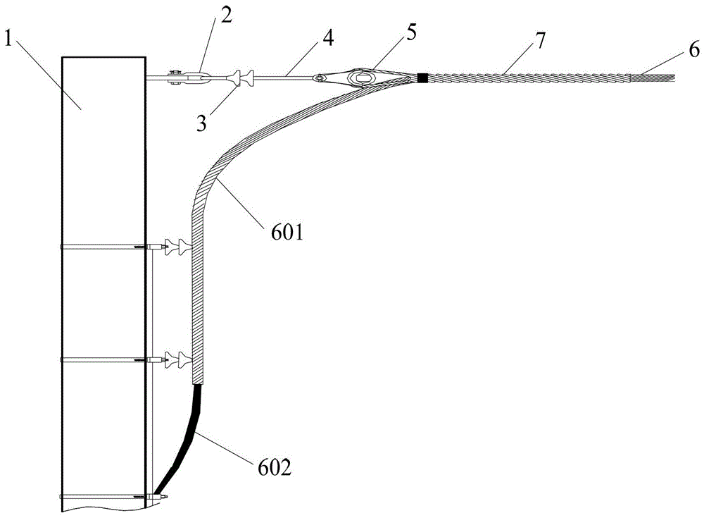
[0046] figure 1 For the schematic structural diagram of the access system from the terminal tower to the substation provided by the embodiment of the present invention, refer to figure 1 , the station entry system may include: a U-shaped hanging ring 2 arranged on the substation outlet frame side 1; an insulator 3 connected to the U-shaped hanging ring 2; an extension rod 4 connected to the insulator 3; The U-shaped connecting ring 5; the composite cable 6 ov...


PUM


Abstract

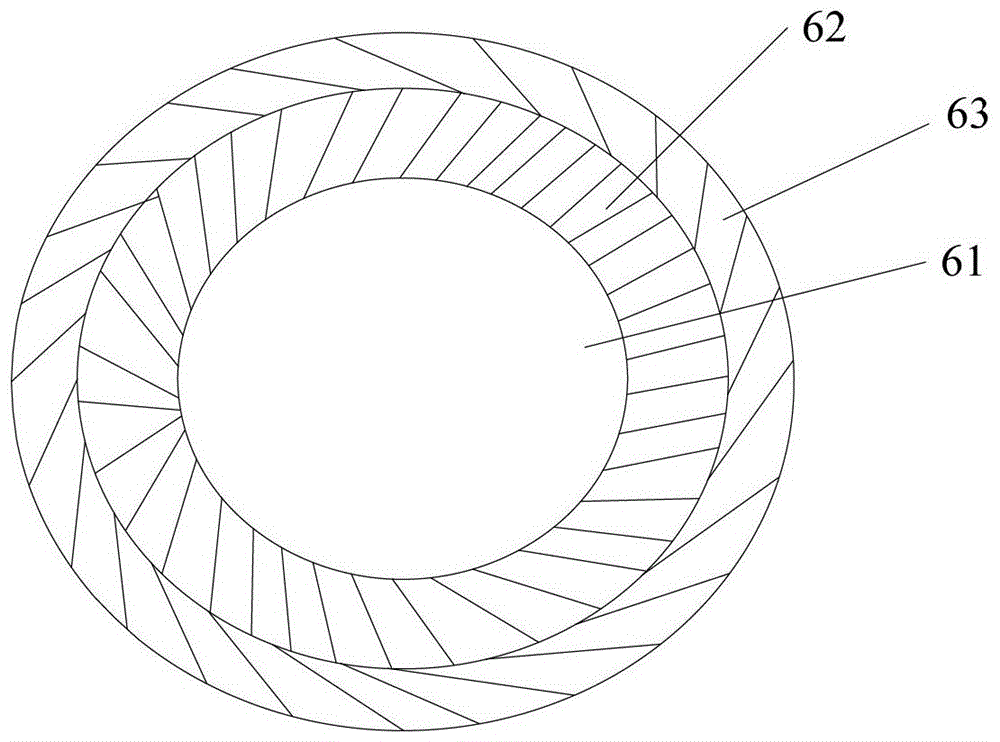
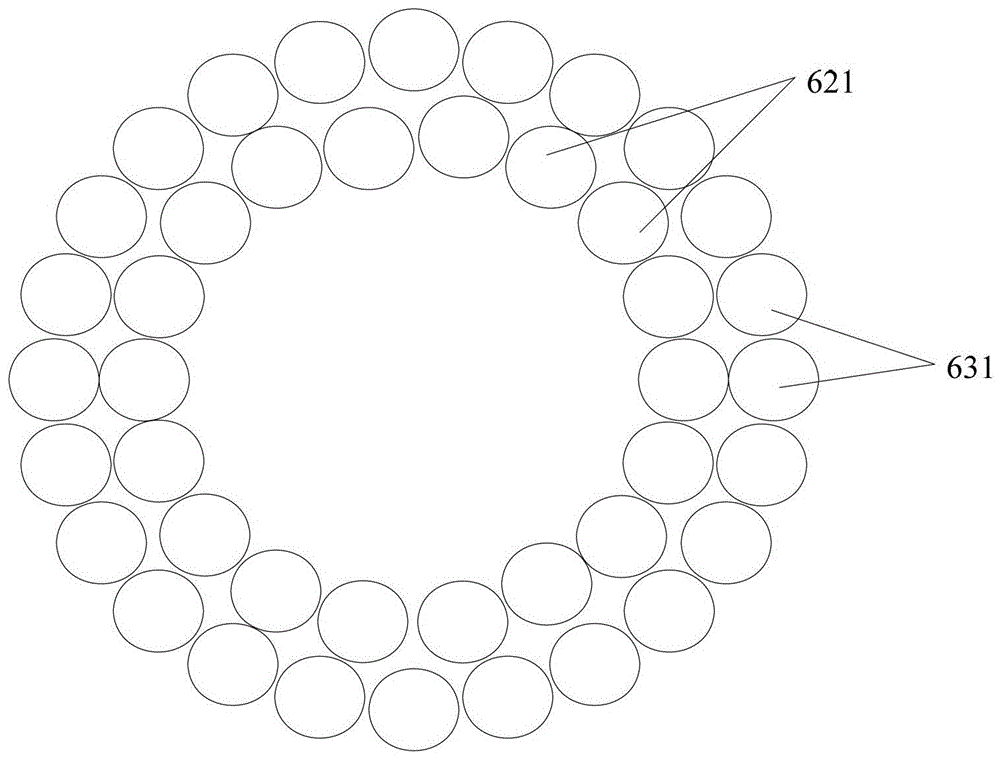
The embodiment of the invention provides an entering system from a terminal tower to a transformer substation. The system comprises a U-shaped hanging ring arranged at the side of an outgoing frame of the transformer substation, an insulator connected with the U-shaped hanging ring, an extension rod connected with the insulator, a U-shaped connecting ring connected with the extension rod, a composite cable which is arranged between the transformer substation and the terminal tower in an overhead manner through the U-shaped connecting ring, and a strain clamp which is used for fixing the composite cable, wherein the composite cable comprises an optical cable, a first ground wire layer coated outside the optical cable, and a second ground wire layer coated outside the first ground wire layer; the composite cable is provided with a grounding composite cable in a leading down state through one side of the U-shaped connecting ring at the side of the outgoing frame of the transformer substation; the composite cable in the leading down state is divided into a first composite cable section in which the first ground wire layer and the second ground wire are maintained, and a second composite cable section in which the first ground wire layer and the second ground wire layer are peeled; and the second composite cable is grounded. According to the embodiment of the invention, the problem that an arrival optical cable is melted and destroyed can be solved, and the requirement on electrical isolation can be fulfilled.

Description

technical field [0001] The invention relates to the technical field of optical cable entry, more specifically, to a station entry system from a terminal tower to a substation. Background technique [0002] At present, the access system from the terminal tower to the substation is mainly realized through the OPGW (Optical Fiber Composite Overhead Ground Wire) optical cable installed overhead between the terminal tower and the substation, so the access system from the terminal tower to the substation is also It is called OPGW pit stop system. [0003] In the OPGW station system, accidents of OPGW melting often occur. This is because the OPGW down-conductor and the frame are in a state of insulation and non-insulation. Under lightning, short circuit, operation and other factors, the OPGW down-conductor will There are two types of induced voltage and current: one is short-term induced voltage and current under factors such as lightning, short circuit, and operation, and the oth...

Claims


Application Information

Patent Timeline
Patent Type & Authority Patents(China)
IPC IPC(8): H02G7/00
Inventor 朱发强叶大革夏翔黄红兵叶忠民毛秀伟王彦波仇钧王坚刚
Owner STATE GRID CORP OF CHINA
Learn More