Tensioning frame suitable for steel sheets of different lengths

A steel sheet and adaptation technology, applied in laser welding equipment, welding/welding/cutting items, manufacturing tools, etc., can solve the problems of cumbersome switching of tensioning frames, etc., and achieve the effect of simple and convenient use and good technical effects

Active Publication Date: 2016-07-06
KUNSHAN THETA MICRO
View PDF5 Cites 0 Cited by
  • Summary
  • Abstract
  • Description
  • Claims
  • Application Information

AI Technical Summary

Problems solved by technology

[0006] The technical problem to be solved by the present invention is the cumbersome problem of switching between the applicable specifications of the tensioning frame due to the different length specifications of the cut steel sheets in the prior art

Method used


Image

  • Tensioning frame suitable for steel sheets of different lengths
  • Tensioning frame suitable for steel sheets of different lengths
  • Tensioning frame suitable for steel sheets of different lengths

Examples


Embodiment 1

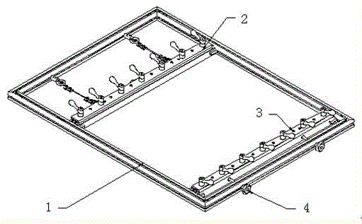
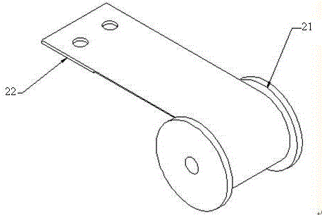
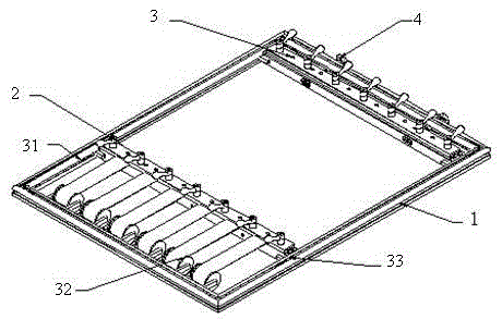
[0027] A kind of tension frame suitable for different length steel sheets, such as figure 2 , 3 As shown, it includes an outer frame, a fixed beam, a movable beam, a constant load spring, a fixed beam guide groove, a fixed beam positioning mechanism, and a drive screw; the two ends of the constant load spring are respectively connected to the fixed beam and the outer frame, and the outer frame has scales , Corresponding to the fixed beam positioning mechanism, the fixed beam positioning mechanism is located between the fixed beam and the constant load spring; the drive screw is located on the outer frame and is connected to the movable beam.

Embodiment 2

[0029] A tension frame suitable for steel sheets of different lengths, including an outer frame, a fixed beam, a movable beam, a constant load spring, a fixed beam guide groove, a fixed beam positioning mechanism, and a drive screw; the two ends of the constant load spring are respectively connected to the fixed beam On the outer frame, the outer frame has a scale corresponding to the fixed beam positioning mechanism. The fixed beam positioning mechanism is located between the fixed beam and the constant load spring; the drive screw is located on the outer frame and is connected to the movable beam.

[0030] In the above scheme, the use of a constant load spring to tension the fixed beam of the tension frame actually changes the meaning of the existence of the movable beam and the fixed beam. The structure of the movable beam does not require major changes. It only needs to add a standard to position the tension state of the steel sheet to ensure that the position of the movable b...


PUM


Abstract

The invention relates to a tension frame suitable for steel sheets with different lengths, which mainly solves the problem of the prior art that the switching of the tension frame between applicable sizes is complicated due to different lengths of the cut steel sheets. The tension frame suitable for the steel sheets with different lengths adopts the technical scheme that the tension frame comprises an outer frame, a fixed beam, a movable beam, a constant load spring, a fixed beam guide groove, a fixed beam positioning mechanism and a driving screw rod, wherein both ends of the constant load spring are respectively connected with the fixed beam and the outer frame, the outer frame is provided with scales corresponding to the fixed beam positioning mechanism, the fixed beam positioning mechanism is positioned between the fixed beam and the constant load spring, and the driving screw rod is positioned on the outer frame and is connected with the movable beam. The problem is well solved, and the tension frame can be widely applied to the laser processing industry.

Description

Technical field [0001] The invention relates to a tension frame suitable for steel sheets of different lengths. Background technique [0002] In the SMT template laser cutting process, the tension frame is used as the carrier of the steel sheet, and its effect greatly affects the processing quality of the steel sheet. The working principle of the tensioning frame is to press the two ends of the steel sheet on two beams, fix one beam, and pull the other beam in the opposite direction of the steel sheet to flatten the steel sheet with tension. Under the action of tensile force, the sagging and corrugation of the steel sheet is reduced to a certain extent, and the flatness of the surface of the steel sheet reaches a certain range, which can meet the needs of use. Such as figure 1 As shown, the middle part of the old tension frame is the steel sheet loading area. The tensioning mechanism is to directly drive the movable beam through the screw to exert tension on the steel sheet. [...

Claims


Application Information

Patent Timeline
Patent Type & Authority Patents(China)
IPC IPC(8): B23K26/70B23K26/38B23K101/18
Inventor 魏志凌宁军蒋勤丰
Owner KUNSHAN THETA MICRO
Why Eureka
Try Eureka