Self-check type auto-passing neutral section system and auto-passing neutral section method of electrified railway
An automatic over-phase, electrified railway technology, applied in power lines, transportation and packaging, vehicle components, etc., can solve problems such as power supply dead zone, mutual influence, loss, etc., to improve system reliability, avoid human interference, and power outages short time effect
- Summary
- Abstract
- Description
- Claims
- Application Information
AI Technical Summary
Problems solved by technology
Method used
Image
Examples
Embodiment 1
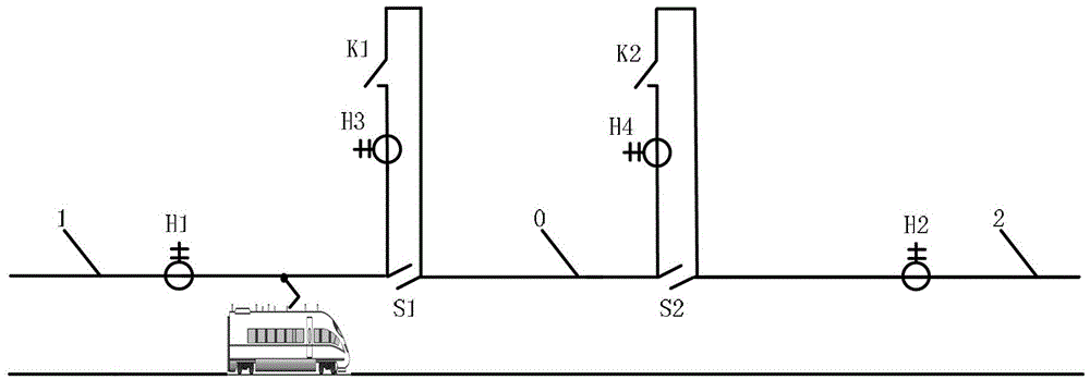
[0028] figure 1 It shows that a specific implementation of the present invention is an electrified railway self-inspection type automatic phase separation system, including catenary one 1, catenary two 2, neutral section 0, catenary one 1 passes through electric segment one S1 is connected to neutral segment 0, and catenary 2 is connected to neutral segment 0 through electrical segment 2 S2, where:
[0029] The catenary-1 is connected in series with the current transformer-H1 near the electric segment-S1, and the current transformer-H3 and the normally open switch-K1 are connected in series and then connected in parallel on the electric segment-S1;
[0030] The catenary 2 2 is connected in series with the current transformer 2 H2 near the electrical segment 2 S2, and the current transformer 4 H4 and the normally open switch 2 K2 are connected in series and then connected in parallel on the electrical segment 2 S2;
[0031] Current transformer one H1, current transformer two H...
Embodiment 2
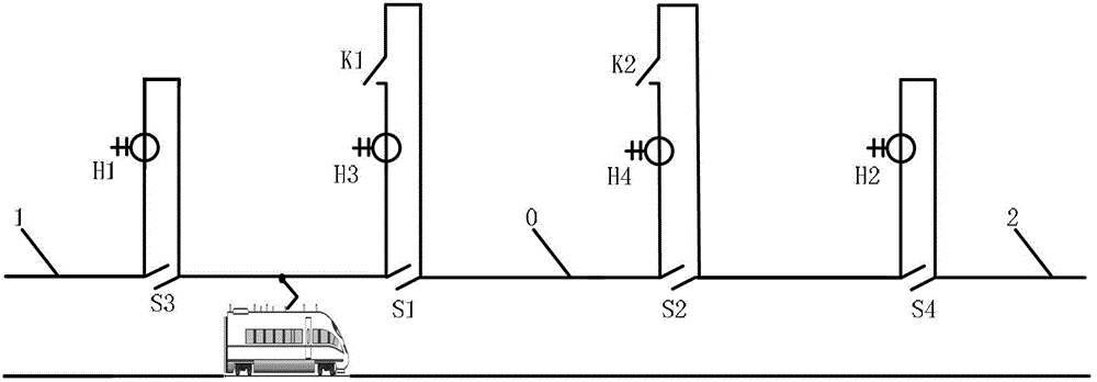
[0041] figure 2 It is shown that the structure of this example is basically the same as that of the first embodiment, the difference is only that the current transformer one H1 is connected in parallel with the third electrical segment S3, and the current transformer two H2 is connected with the fourth electric segment S4 in parallel.
[0042] In this way, electric segment three S3 and electric segment four S4 can be connected in series in catenary one 1 and catenary two 2 respectively, while current transformer one H1 and current transformer two H2 are respectively connected in parallel in electric segment three S3 , Electric segment four S4 on. Thereby, the connection of the catenary here is smoother, and the train can take the flow more reliably.
[0043] In order to reduce contact line segmentation, current transformer 1 H1 and current transformer 2 H2 can be implemented as clamp-type current transformers. The shunt relationship between the contact wires measures the cu...
PUM
 Abstract
Description
Claims
Application Information
 - R&D
- Intellectual Property
- Life Sciences
- Materials
- Tech Scout
- Unparalleled Data Quality
- Higher Quality Content
- 60% Fewer Hallucinations
Browse by: Latest US Patents, China's latest patents, Technical Efficacy Thesaurus, Application Domain, Technology Topic, Popular Technical Reports.
© 2025 PatSnap. All rights reserved.Legal|Privacy policy|Modern Slavery Act Transparency Statement|Sitemap|About US| Contact US: help@patsnap.com


