
Oil-gas separation gear and engine provided with same

A technology for separating gears and engines, which is applied to the lubrication of engine components, machines/engines, and engines. It can solve the problems of reducing engine life, lubricating oil loss, and component wear, and achieves increased service life, smooth lubrication, and solution The effect of oil loss

Active Publication Date: 2013-09-11
CHINA HANGFA SOUTH IND CO LTD
View PDF4 Cites 0 Cited by
  • Summary
  • Abstract
  • Description
  • Claims
  • Application Information

AI Technical Summary

Problems solved by technology

During the cycle, there will be oil and gas generated by lubrication in the inner chamber of the engine. In order to separate the air and oil droplets, an oil and gas separation device is needed to prevent the exhaust gas from taking the lubricating oil out of the engine, resulting in loss of lubricating oil, poor engine lubrication, and parts. wear, reducing engine life

Method used


Image

  • Oil-gas separation gear and engine provided with same
  • Oil-gas separation gear and engine provided with same
  • Oil-gas separation gear and engine provided with same

Examples


Embodiment Construction

[0022] The embodiments of the present invention will be described in detail below with reference to the accompanying drawings, but the present invention can be implemented in many different ways defined and covered by the claims.

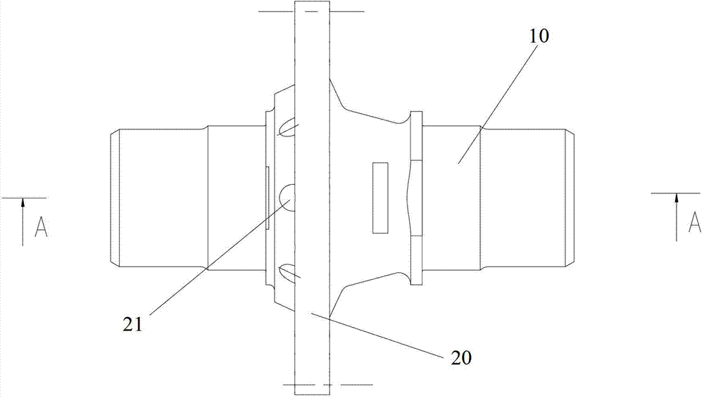
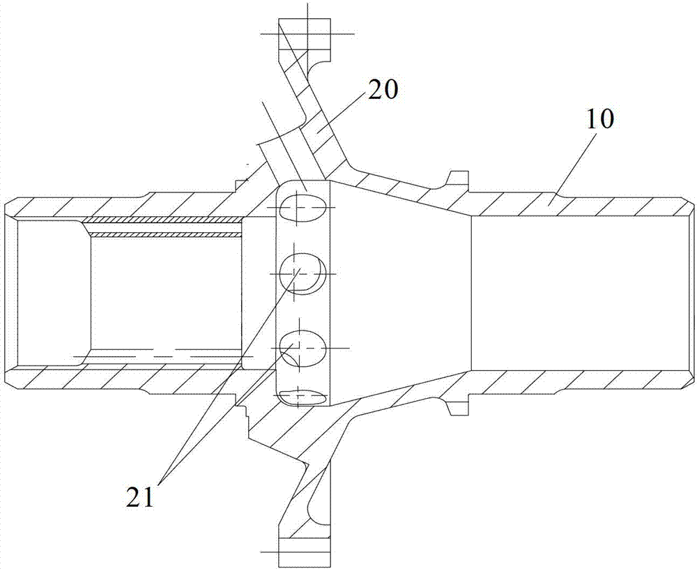
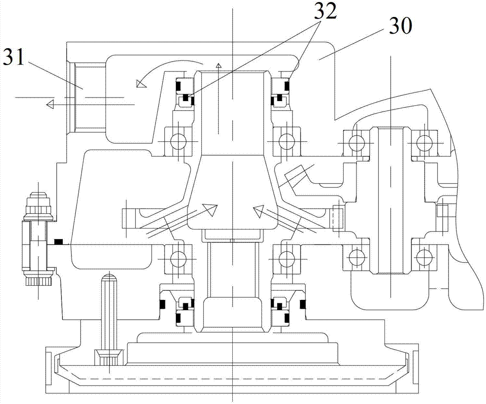
[0023] see Figure 1 to Figure 2 , according to the oil-gas separation gear of the present invention, comprising: a gear shaft 10, the gear shaft 10 is a hollow structure; a web 20 is arranged on the gear shaft 10, and the web 20 is provided with an inlet connected to the hollow structure of the gear shaft 10. There is an angle between the axial direction of the air oil rejection hole 21 and the axial direction of the air inlet oil rejection hole 21 and the gear shaft 10 . The material of the oil-gas separation gear is structural steel. The oil-gas separation gear of the present invention condenses the oil in the oil-gas mixture that enters through the air intake oil rejection hole on the wall of the air intake oil rejection hole through high-speed ...


PUM

PropertyMeasurementUnit
Diameteraaaaaaaaaa
Diameteraaaaaaaaaa

Abstract

The invention provides an oil-gas separation gear and an engine provided with the oil-gas separation gear. The oil-gas separation gear comprises a gear shaft and a spoke plate, wherein the gear shaft is of a hollow structure, the spoke plate is arranged on the gear shaft and is provided with an air-inlet and oil-slinger hole which is communicated with the hollow structure of the gear shaft, and an angle is formed between the axial direction of the air-inlet and oil-slinger hole and the axial direction of the gear shaft. The engine comprises the oil-gas separation gear. According to the oil-gas separation gear, oil in oil-gas combined gas entering the oil-gas separation gear from the air-inlet and oil-slinger hole is congealed on the hole wall of the air-inlet and oil-slinger hole through high-speed rotation, and the oil is congealed to be oil drops, slung back into the engine through the air-inlet and oil-slinger hole and then recycled and reused, so that radial entering of the oil-gas combined gas and radial discharge of waste gas are achieved, the loss problem of lubricating oil of the engine is effectively solved, the engine is lubricated smoothly, and the service life of the engine is prolonged.

Description

technical field [0001] The invention relates to the field of engines, in particular to an oil-gas separation gear and an engine with the oil-gas separation gear. Background technique [0002] The main function of the lubricating oil system of a certain type of engine in the prior art is to lubricate and cool the engine parts such as bearings and gears with relatively moving working surfaces, and a circulating lubricating oil system is adopted. During the cycle, there will be oil and gas generated by lubrication in the inner chamber of the engine. In order to separate the air and oil droplets, an oil and gas separation device is needed to prevent the exhaust gas from taking the lubricating oil out of the engine, resulting in loss of lubricating oil, poor engine lubrication, and parts. Wear and reduce engine life. Contents of the invention [0003] The purpose of the present invention is to provide an oil-air separation gear and an engine with the oil-air separation gear, s...

Claims


Application Information

Patent Timeline
IPC IPC(8): F01M11/08
Inventor 王运知张艳张伟郜雪鹏熊海
Owner CHINA HANGFA SOUTH IND CO LTD
Learn More