belt head structure

A belt head and step surface technology, applied to buckles, clothing, applications, etc., can solve problems such as inability to find positions and patterns that cannot be aligned in the positive direction, and achieve the effect of increasing willingness to buy and increase willingness to buy

Inactive Publication Date: 2016-12-14
苏永发
View PDF4 Cites 0 Cited by
  • Summary
  • Abstract
  • Description
  • Claims
  • Application Information

AI Technical Summary

Problems solved by technology

[0005] The present invention aims to solve the technical problem of improving the existing ring body on the upper end surface of the belt head, which cannot be located after being absorbed, so that the pattern cannot be aligned in the forward direction, and it needs to be removed and re-placed before it can be positioned in the forward direction. For this reason, The present invention provides that the ring body can be located in the forward direction and can be positioned by adsorption in the forward direction and can be removed freely, and the layers of the ring body can be aligned in the forward direction

Method used


Image

  • belt head structure
  • belt head structure
  • belt head structure

Examples


Embodiment Construction

[0034] In the following, specific embodiments will be described in detail in conjunction with the attached drawings, and it will be easier to understand the purpose, technical content, features and effects of the present invention.

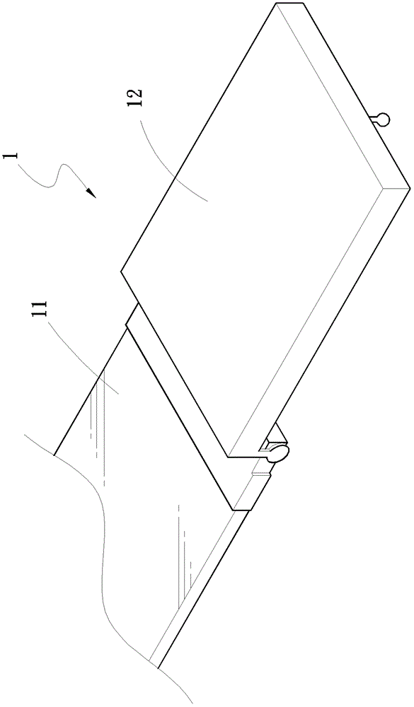
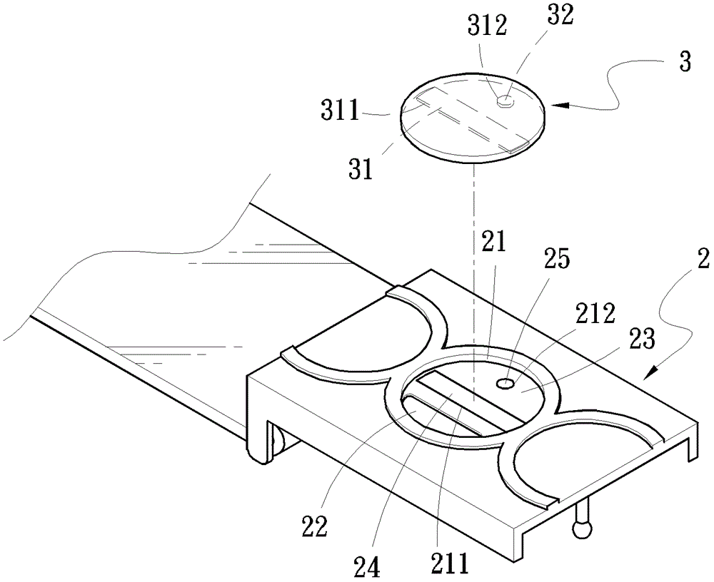
[0035] refer to figure 2 and image 3 , Figure 4 As shown, the belt head structure of the preferred embodiment of the present invention includes a belt head 2 and a ring body 3, wherein

[0036] The upper end surface of the belt head 2 forms a groove 21, and forms a first stepped surface 22 and a second stepped surface 23 of different heights in the groove 21, and the height of the second stepped surface 23 is higher than the The first step surface 22 is high, and the second step surface 23 is provided with a first concave surface 211 located at the center of the groove 21. In the embodiment of this case, the first concave surface 211 is set as a strip, which can be used for The first positioning magnet 24, which is strip-shaped and positive,...


PUM


Abstract

The invention discloses a belt fastener structure. The belt fastener structure comprises a belt fastener and an annular body; a groove is formed in the upper end surface of the belt fastener; a first step surface and a second step surface are formed in the groove; the first step surface and the second step surfaced are in different heights; the higher second step surface is provided with a first positioning magnet and a second positioning magnet; the annular body which is locatable can be forwardly located at the groove of the belt fastener; accordingly the annular body can be freely taken down or fixed, a user can conveniently take and use at any time when having requirements or choosing, using functions of a belt are increased, and the problem that a pattern of the annular body on the upper end surface of the existing belt fastener cannot be aligned towards the forward location is solved.

Description

technical field [0001] The invention relates to a belt head structure, in particular to a belt head for a ring body which can be positioned in the forward direction, absorbed and fixed, and taken off freely. Background technique [0002] Commonly used belts 1, such as figure 1 Shown, be that a belt head 12 is fixedly set at an end of belt body 11, pass belt head 12 fixed position by the other end of belt body 11, though belt 1 can bind trousers firmly, this is only the original of belt 1 Therefore, belt manufacturers will change the material of the belt body 11, the fixing method or shape of the belt head 12, and set the belt 1 as a multi-functional trend, but it is still not enough to attract Consumers want to buy, and some manufacturers will print patterns on the end surface of the belt head 12 to improve the appearance or as a manufacturer's logo, so as to change the structure of the belt 1 to improve the functionality of the belt 1 . [0003] For this reason, the inven...

Claims


Application Information

Patent Timeline
Patent Type & Authority Patents(China)
IPC IPC(8): A44B11/00
Inventor 苏永发
Owner 苏永发
Why Eureka
Try Eureka