Living body eye retina high-resolution imaging system with two wavefront correctors

A high-resolution, eye-retinal technology, applied in ophthalmoscopes, eye testing equipment, medical science, etc., can solve problems that affect system correction effects, complex control process, and poor measurement accuracy of wavefront sensors, and achieve improved Aberration correction capability, simple system, and easy-to-achieve effects

Active Publication Date: 2015-05-06
INST OF OPTICS & ELECTRONICS - CHINESE ACAD OF SCI
View PDF12 Cites 0 Cited by
  • Summary
  • Abstract
  • Description
  • Claims
  • Application Information

AI Technical Summary

Problems solved by technology

The control of the two wavefront correctors by the system is based on the human eye aberration measured by the wavefront sensor. At the same time, when the system controls the two wavefront correctors, the coupling effect between the two wavefront correctors needs to be eliminated, and the control process is relatively complicated.

Method used


Image

  • Living body eye retina high-resolution imaging system with two wavefront correctors
  • Living body eye retina high-resolution imaging system with two wavefront correctors
  • Living body eye retina high-resolution imaging system with two wavefront correctors

Examples


Embodiment Construction

[0028] In order to illustrate the implementation process of the present invention clearly and in detail, some specific embodiments of the present invention are given below. The preferred embodiments of the present invention will be described in detail below with reference to the accompanying drawings, and unnecessary details and functions for the present invention will be omitted during the description to avoid confusing the understanding of the present invention.

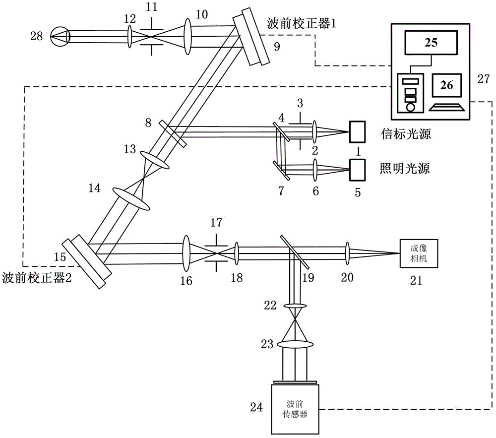
[0029] Such as figure 1 As shown, the high-resolution imaging system of the living human eye retina with a dual wavefront corrector consists of a near-infrared beacon light source 1, a collimating mirror 2, a beacon diaphragm 3, a first beam splitter 4, an illumination light source 5, and a collimating mirror 6 , plane mirror 7, second beam splitter 8, first wavefront corrector 9, first lens 10, first confocal filter diaphragm 11, second lens 12, third lens 13, fourth lens 14, the first Two wavefront correctors 15, ...


PUM


Abstract

The invention relates to a living body eye retina high-resolution imaging system with two wavefront correctors. The living body eye retina high-resolution imaging system with two wavefront correctors comprises a beacon luminous emission subsystem, a control subsystem and an illuminating imaging subsystem. The beacon luminous emission subsystem provides a beacon light source for eye aberration measuring and rectification. The control subsystem controls the two wavefront correctors to rectify eye aberration. A lighting source provides optical radiation and enters the eye lighting retina through an optical path, and an imaging system and a camera are used for shooting an eye ground retina high-resolution image. The two wavefront rectifying devices adopt different control algorithms. Based on a beacon optical image obtained by the imaging camera, the first wavefront rectifying device selects an objective function and performs controlling with the optimizing algorithm to rectify eye low-order aberration. After rectification is finished, the first wavefront corrector is kept fixed. Left eye aberration is measured by a wavefront sensor and the second wavefront rectifying device is controlled to rectify the left eye aberration in real time. After rectification is stable or reaches the preset value, the lighting imaging subsystem is started to shoot the eye ground retina high-resolution image. The living body eye retina high-resolution imaging system of the two wavefront rectifying devices effectively improves the aberration rectifying capability of the system.

Description

technical field [0001] The invention relates to an adaptive optical fundus imaging technology, which is a high-resolution imaging system of a living human eye retina with a double wavefront corrector, and can be widely used for high-resolution imaging of a living human eye retina. Background technique [0002] In addition to low-order aberrations such as defocus and astigmatism, human eye aberrations also contain high-order aberration components that cannot be ignored. At present, ordinary commercial ophthalmic equipment such as fundus cameras can only statically compensate low-order human eye aberrations, so the overall optical resolution cannot reach the diffraction-limited level. Adaptive optics technology just makes up for this defect and directly promotes the development of fundus imaging and optometry. In 1997, D.R.Williams of the University of Rochester in the United States took the lead in the world to use Adaptive Optics (AO) technology to correct the high-order ab...

Claims


Application Information

Patent Timeline
Patent Type & Authority Patents(China)
IPC IPC(8): A61B3/12A61B3/15
Inventor 张雨东肖飞戴云赵军磊康健赵豪欣
Owner INST OF OPTICS & ELECTRONICS - CHINESE ACAD OF SCI
Why Eureka
Try Eureka