Optical system and theory for checking aspheric mirror through conjugate correction

A technology of aspheric mirror and optical system, which is applied in the field of aspheric mirror inspection, and can solve the problems of reducing compensation (correction) ability, etc.

Pending Publication Date: 2019-12-17
SHANGHAI INST OF TECHNICAL PHYSICS - CHINESE ACAD OF SCI
View PDF0 Cites 2 Cited by
  • Summary
  • Abstract
  • Description
  • Claims
  • Application Information

AI Technical Summary

Problems solved by technology

The zero position compensation test is divided into two intervals, the front zero position compensation test and the rear zero position compensation test. The two intervals are irrelevant, whi

Method used


Image

  • Optical system and theory for checking aspheric mirror through conjugate correction
  • Optical system and theory for checking aspheric mirror through conjugate correction
  • Optical system and theory for checking aspheric mirror through conjugate correction

Examples


Example Embodiment

[0049] The invention proposes an optical system and basic theory for conjugate correction and inspection of aspheric mirrors. The present invention will be further described in detail below in conjunction with the drawings and specific embodiments. The specific embodiments described are only used to explain the present invention, but not used to limit the present invention.

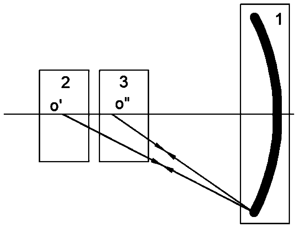
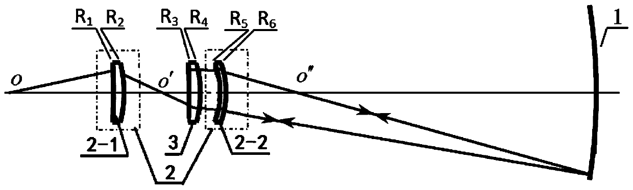
[0050] The self-collimating lens 3 and the second correcting lens 2-2 are located at the center of the concave aspheric surface to be inspected. Such as figure 2 As shown, the light is emitted from the point O on the axis and passes through the spherical surface R of the first correcting lens 2-1 1 With spherical R 2 Spherical surface R of transmission and auto-collimation lens 3 3 With R 4 Transmission, and the spherical surface R of the second correction lens 2-2 5 With R 6 It is refracted to the concave aspheric mirror to be inspected 1 (the virtual image is at the conjugate back point O'of the concave ...


PUM


Abstract

The invention discloses an optical system and theory for checking an aspheric mirror through conjugate correction. Light emitted by a light-emitting point in detection equipment is imaged on a conjugate object point of a to-be-detected aspheric mirror through a correction lens; the to-be-detected aspheric mirror images the conjugate object point on a conjugate image point; and the conjugate imagepoint is used as an object point of an auto-collimation correction lens and light is returned along an auto-collimation original path of the auto-collimation correction lens. The spherical aberrationgenerated by the correction lens and the auto-collimation correction lens can correct the spherical aberration generated by the to-be-detected aspheric mirror at two conjugate points. The conjugate front and back points are related to a front region, a middle region and a back region, so that the aberration correction capability is greatly improved. The auto-collimation surface is formed on the auto-collimation correction lens and light passes through the to-be-detected aspheric mirror twice. The auto-collimation correction lens is arranged in front of the conjugate front point, so that the oblate spherical surface correction capacity is high. The correction lens is in light path connection with the auto-collimation correction lens, so that the correction capability is enhanced. The conjugate correction checking can test an aspheric mirror with a large aperture, a large relative aperture or even an ultra-large aperture and an ultra-large relative aperture.

Description

Technical field [0001] The invention relates to the inspection of aspheric mirrors with large apertures and large relative apertures, and even inspections of aspheric mirrors with super-large apertures and relatively large relative apertures, and specifically refers to the basic theory of testing aspheric mirrors based on the principle of conjugate correction. Background technique [0002] Aspheric lens optics includes the main parts of aberration theory, aspheric lens optical system design, auxiliary optical system design, processing technology and image quality evaluation. Among them, auxiliary optical system design serves as a bridge between aspheric lens optical system design and aspheric lens processing. The processing of designing aspherical mirrors is realized by the auxiliary optical system to inspect the aspherical mirrors. Looking back at the development history of auxiliary optical system design, aspheric lens inspection can be divided into two main types: [0003] 1. C...

Claims


Application Information

Patent Timeline
IPC IPC(8): G02B27/00G01M11/02
CPCG01M11/02G02B27/0025
Inventor 郝沛明郑列华
Owner SHANGHAI INST OF TECHNICAL PHYSICS - CHINESE ACAD OF SCI
Why Eureka
Try Eureka