An anti-accident safety structure
A safety structure and unexpected technology, which is applied in the direction of liquid displacement machinery, pump control, machine/engine, etc., can solve the problems of easy safety accidents, the installation of safety protection valves without considering the cost, etc., and achieve fast unloading and fast pumping The effect of internal pressure
- Summary
- Abstract
- Description
- Claims
- Application Information
AI Technical Summary
Problems solved by technology
Method used
Image
Examples
Embodiment 1
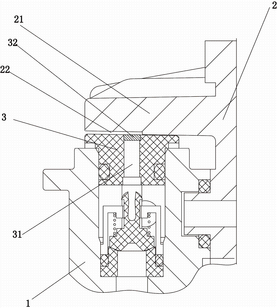
[0013] Embodiment 1: see figure 1 As shown, an accident-proof safety structure includes a pump cover 1 and a plunger frame 2. A water outlet valve 3 is fixedly arranged on the pump cover 1. A safety hole 31 is arranged on the water outlet valve 3. A water outlet valve is arranged above the safety hole 31. 3. Sealed and fixedly connected safety element 32. The plunger frame 2 is provided with a plunger frame front cover plate 21, the plunger frame front cover plate 21 is covered on the water outlet valve 3, the plunger frame front cover plate 21 is provided with an overflow groove 22, the overflow groove 22 above the safety element 32 . When an unexpected situation occurs in the high-pressure plunger pump, the high-pressure water in the pump cover 1 will break through the safety member 32 , and the high-pressure water will flow out through the overflow groove 22 after breaking through the safety member 32 .
Embodiment 2
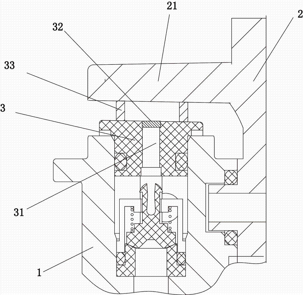
[0014] Example 2: see figure 2 As shown, the plunger frame 2 is provided with a plunger frame front cover plate 21 , and the water outlet valve 3 is provided with several support columns 33 , and the plunger frame front cover plate 21 covers the support columns 33 . When an accident occurs in the high-pressure plunger pump, the high-pressure water in the pump cover 1 will break through the safety member 32 through the safety hole 31 , and the high-pressure water will flow out through the gap between the support columns 33 after breaking through the safety member 32 . Other features are consistent with Example 1.
Embodiment 3
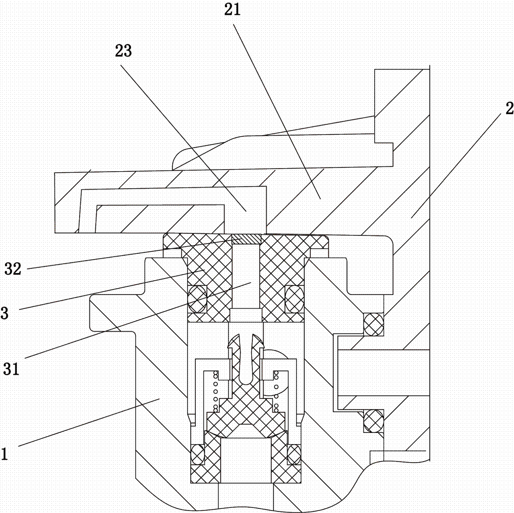
[0015] Embodiment 3: see image 3 As shown, the plunger frame 2 is provided with a plunger frame front cover plate 21, the plunger frame front cover plate 21 covers the water outlet valve 3, and the plunger frame front cover plate 21 is provided with a pressure transmission through hole 23 , the pressure transmission through hole 23 is disposed above the safety element 32 . The diameter of the end of the pressure transmitting through hole 23 close to the safety element 32 is larger than that of the safety element 32 . When an accident occurs in the high-pressure plunger pump, the high-pressure water in the pump cover 1 will break through the safety member 32 through the safety hole 31 , and the high-pressure water will flow out through the pressure transmission hole 23 after breaking through the safety member 32 . This is that other equipment can be connected in addition at the pressure transmission through hole 23, so that the high-pressure water can be gathered in one place...
PUM
 Abstract
Description
Claims
Application Information
 - R&D
- Intellectual Property
- Life Sciences
- Materials
- Tech Scout
- Unparalleled Data Quality
- Higher Quality Content
- 60% Fewer Hallucinations
Browse by: Latest US Patents, China's latest patents, Technical Efficacy Thesaurus, Application Domain, Technology Topic, Popular Technical Reports.
© 2025 PatSnap. All rights reserved.Legal|Privacy policy|Modern Slavery Act Transparency Statement|Sitemap|About US| Contact US: help@patsnap.com


